
Battery and method for manufacturing spiral electrode group for use therein

a spiral electrode and spiral electrode technology, applied in the field of batteries, can solve the problems of deterioration or variation of battery capacity, uneven electrode reaction, and relative low heavy load characteristics, and achieve the effects of preventing uneven charge/discharge reaction, high load characteristics of batteries, and smooth and evenly impregnated

Inactive Publication Date: 2009-03-10
PANASONIC CORP
View PDF18 Cites 12 Cited by
  • Summary
  • Abstract
  • Description
  • Claims
  • Application Information

AI Technical Summary

Benefits of technology

"The present invention relates to a battery with a wound electrode group. The technical effects of the invention include: a clearance or looseness in the wound electrode group that prevents uneven charge / discharge reaction and improves the high load characteristics of the battery; a sealing plate that prevents buckling and short circuits across the positive and negative electrode plates and improves the energy efficiency of the battery; and a method of manufacturing the wound electrode group that allows for easy and good productivity."

Problems solved by technology

Electrode assemblies conventionally used in prismatic batteries are mostly laminated types, having strips of stacked positive and negative electrode plates with separators interposed therebetween, and they have relatively low heavy load characteristics and cannot accept a rapid charge because of the small electrode reaction area.
The above wound electrode group of prismatic shape is manufactured by winding positive and negative electrode plates around a core that has a circular or elliptic cross section, and by compressing the wound assembly so that its circular or elliptic cross section becomes prismatic; with this method, however, the electrodes are often misaligned or brought out of contact near bent portions on the inside, whereby the electrode reaction is made uneven, leading to deterioration or variation of battery capacity.
This trouble may be prevented in the cylindrical wound electrode group of Japanese Patent Laid-Open Publication No. 60-180071 by the adhesive tape tightly wound around the assembly, but the battery capacity is lowered by the use of adhesive tape because of decreased package ratio of the battery, and moreover, when inserting the assembly into the battery case, the assembly loosens more than required when part of the adhesive tape and separator is cut, creating gaps between adjacent positive and negative electrode plates, whereby the electrode reaction is made uneven, leading to deterioration or variation of battery capacity.
This is because gaps between adjacent positive and negative electrode plates make the electrode reaction uneven and lead to deterioration or variation of battery capacity.
While cracks at the winding start can be reduced by retaining the tightly wound state of the assembly with adjacent positive and negative electrode plates in tight contact with each other as in the inventions disclosed in Japanese Patent Laid-Open Publication Nos. 6-96801, 8-171917, and 10-302827, there are the following problems: Firstly, the tightly wound assembly of thin positive and negative electrode plates and separators can hardly be impregnated with electrolyte in the electrolyte injecting process in the manufacture of the battery, and the charge / discharge reaction of the complete battery may become uneven and high load characteristics may be deteriorated because of the uneven impregnation of electrolyte.
This buckling causes large gaps particularly in the center of the prismatic wound electrode group 50, whereby the positive and negative electrode plates separate from each other, making the electrode reaction uneven and lowering the charge / discharge cycle characteristics.
Moreover, a buckling deformation may damage the separator and cause short circuits across the positive and negative electrode plates.
Further troubles caused by the buckling include an outward bulge of the wound electrode group 50 in the central portion, abnormal deterioration of the battery because of a large deformation from the predetermined battery case dimensions, and the possibility of electrical disconnection of the battery from the battery holder case of the equipment because of the deformation of the battery case.
As noted above in relation to the prismatic wound electrode group 50, such buckling makes the electrode reaction uneven and causes various troubles such as deterioration of charge / discharge cycle characteristics and short circuits across the positive and negative electrode plates due to the damaged separator.

Method used


Image

  • Battery and method for manufacturing spiral electrode group for use therein
  • Battery and method for manufacturing spiral electrode group for use therein
  • Battery and method for manufacturing spiral electrode group for use therein

Examples


first embodiment

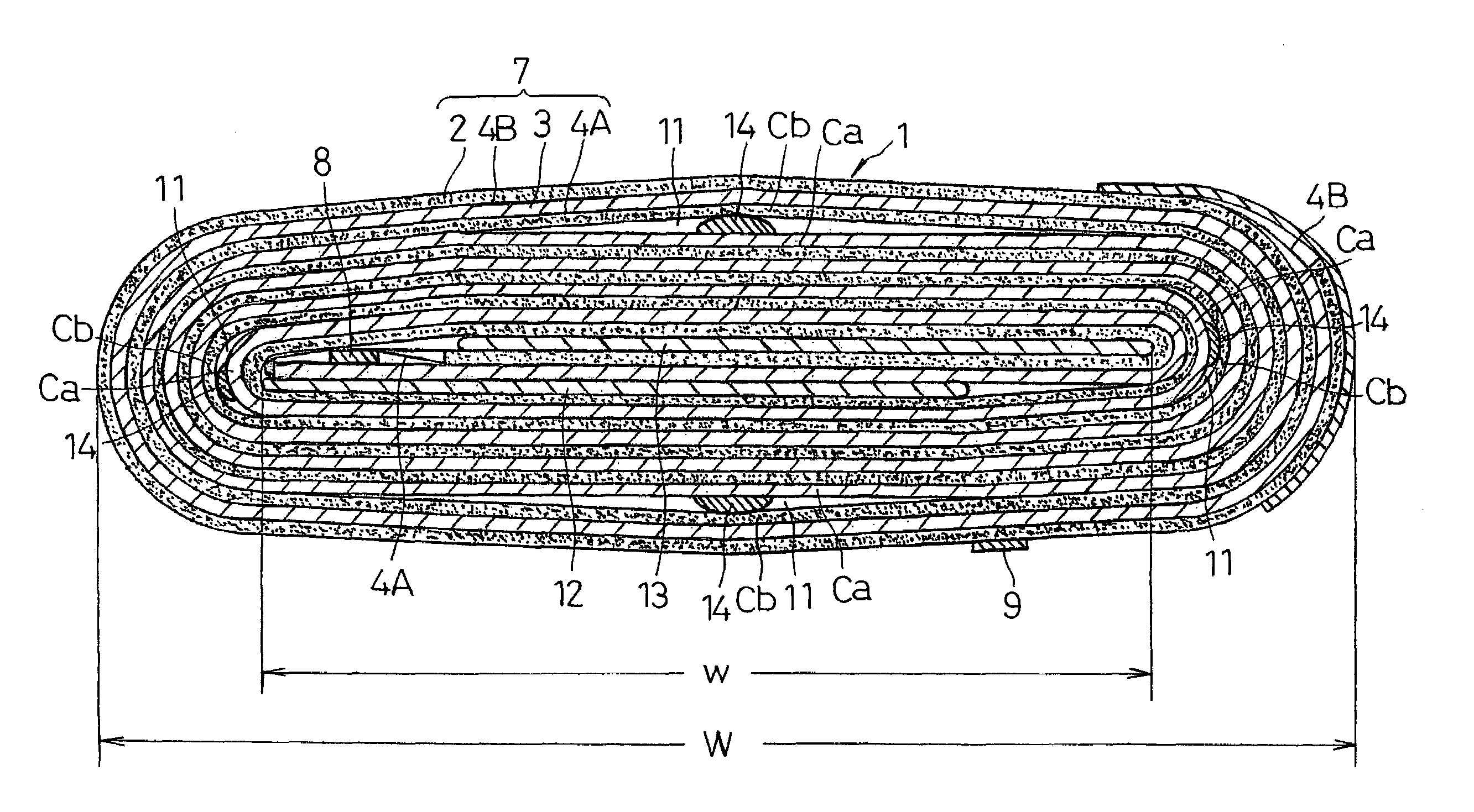
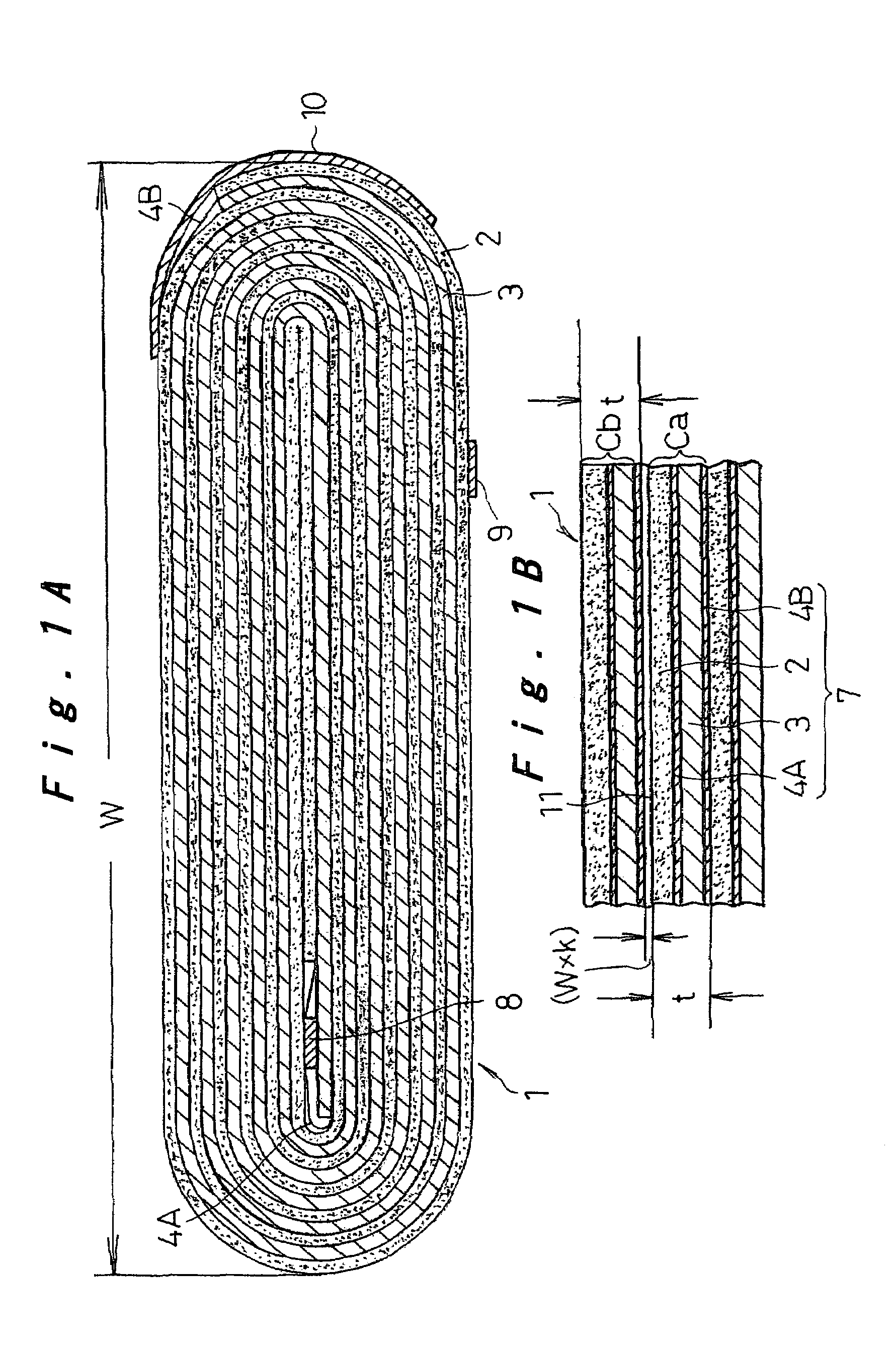
[0035]Preferred embodiments of the present invention will be hereinafter described with reference to the drawings. FIG. 1A is a cross sectional view of a wound electrode group 1 used for a battery according to the invention, and FIG. 1B is an enlarged view of part of FIG. 1A. This embodiment shows one example of a prismatic wound electrode group 1 used for a prismatic battery. The assembly 1 consists of an electrode stack 7 including a strip of positive electrode plate 2, negative electrode plate 3, and a pair of separators 4A, 4B interposed therebetween, wound into a shape having an oval cross section as shown in FIG. 1A. The drawing shows one example of a prismatic wound electrode group 1 for a lithium rechargeable battery; leads 8, 9 are attached to the winding start of the negative electrode plate 3 and the winding end of the positive electrode plate 2, respectively. The winding end of both electrode plates 2, 3 is fixed with a fixing tape (fixing member) 10 attached thereto.

[00...

second embodiment

[0060]FIG. 7A is a cross sectional view of a wound electrode group 30 used for the battery according to the invention, in a state after a winding process in the manufacturing method of the assembly, and FIG. 7B is a cross sectional view of the assembly 30 constructed and used as the battery. This embodiment shows one example of a cylindrical wound electrode group 30 having a circular cross section used for a cylindrical battery; elements corresponding to those shown in FIG. 1A, FIG. 1B, and FIG. 4 are given the same reference numerals in FIG. 7A and FIG. 7B. Also, FIG. 7A and FIG. 7B are schematic representations as with FIG. 1A, FIG. 1B and FIG. 4 for ease of understanding of the structure.

[0061]Manufacturing of the cylindrical wound electrode group 30 starts with a winding process: Strips of positive and negative electrode plates 2, 3 and a pair of separators 4A, 4B interposed therebetween are laminated to form an electrode stack 7; the stack is fixed at a portion one half turn fr...

third embodiment

[0068]FIG. 8A is a cross sectional view of a wound electrode group 33 used for the battery according to the invention, in a state after a winding process in the manufacturing method of the assembly, and FIG. 8B is a cross sectional view of the assembly 33 constructed and used as the battery. This embodiment shows one example of a rounded prismatic wound electrode group 33 having a substantially square cross section with four rounded corners, used for a rounded prismatic battery; elements corresponding to those shown in FIG. 1A, FIG. 1B, and FIG. 4 are given the same reference numerals in FIG. 8A and FIG. 8B. Also, FIG. 8A and FIG. 8B are schematic representations as with FIG. 1A, FIG. 1B and FIG. 4 for ease of understanding of the structure.

[0069]Manufacturing of the rounded prismatic wound electrode group 33 starts with a winding process: Strips of positive and negative electrode plates 2, 3 and a pair of separators 4A, 4B interposed therebetween are laminated to form an electrode ...


PUM

PropertyMeasurementUnit
diameteraaaaaaaaaa
diameteraaaaaaaaaa
heightaaaaaaaaaa

Abstract

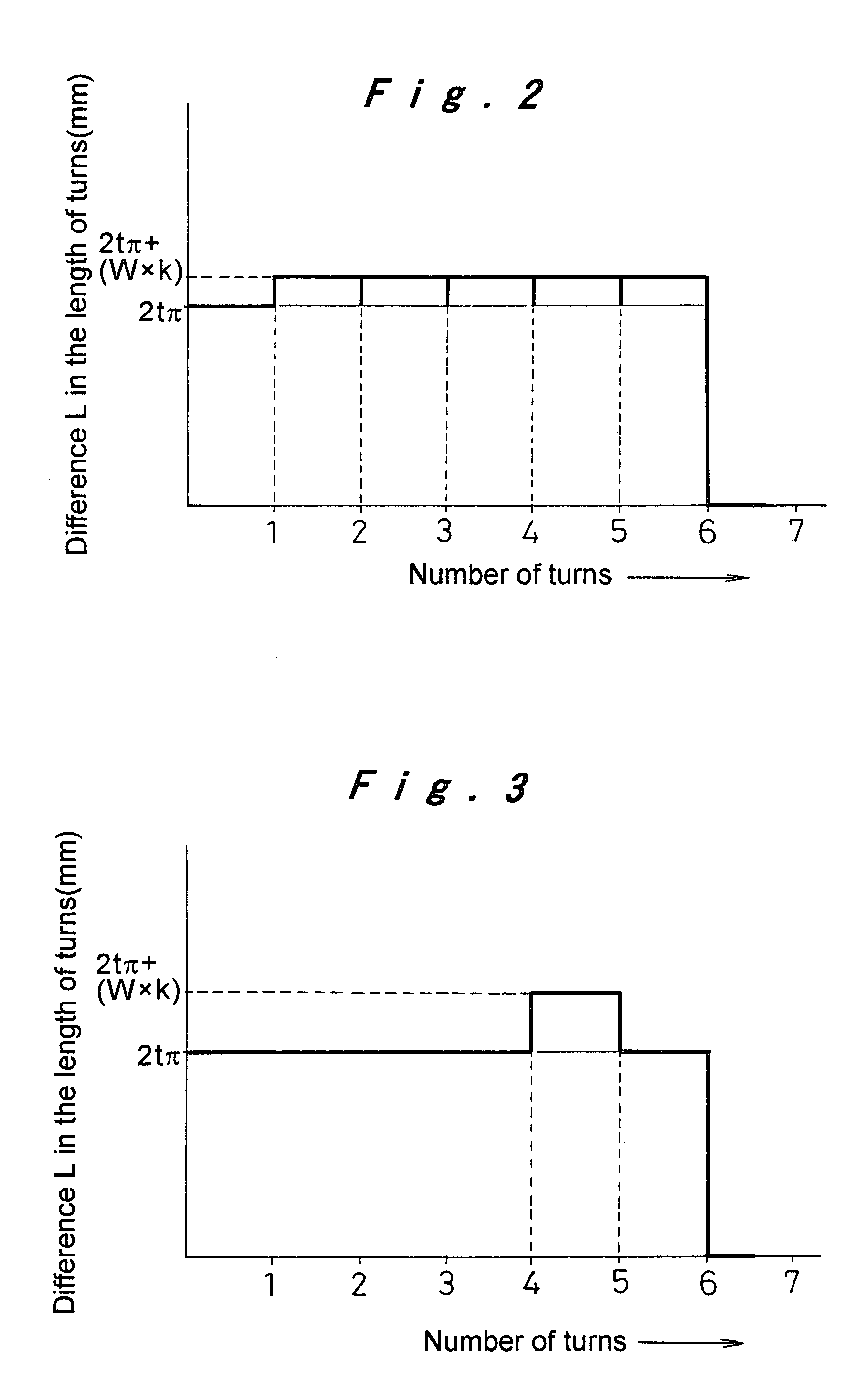
A wound electrode group includes an electrode stack that is formed by laminating a strip of positive electrode plate, a strip of negative electrode plate, and a pair of separators interposed therebetween. When the electrode stack is wound, a difference L in length between an inner turn and an adjacent outer turn satisfies L=2tπ+(W×k), where t is a thickness of the electrode stack, W is a maximum diameter of a cross section of the wound electrode group, and k is a coefficient that is preset in accordance with expansion coefficients of active materials of the positive and negative electrode plates and is within a range from 0.005 to 0.05.

Description

TECHNICAL FIELD[0001]The present invention relates to a battery formed of a wound electrode group accommodated in a battery case, and a suitable method of manufacturing the wound electrode group for use in this battery with good productivity.BACKGROUND ART[0002]Electrical equipment such as audio-visual equipment or PCs and mobile communication devices have rapidly become portable and cordless in recent years. Aqueous electrolyte batteries such as nickel cadmium or nickel metal hydride batteries have been mainly used as the drive power source of these electrical equipment in the past, but these batteries have been replaced recently by non-aqueous electrolyte batteries, typically represented by lithium rechargeable batteries that can be charged rapidly and have high volume / weight energy densities. The nickel cadmium or nickel metal hydride batteries, on the other hand, are being more and more specifically used for power tools or electric vehicles that need a drive power source with hi...

Claims


Application Information

Patent Timeline
Patent Type & Authority Patents(United States)
IPC IPC(8): H01M6/12H01M10/00H01M6/46H01M4/82H01M6/00H01M10/04H01M2/08H01M2/14H01M6/10
CPCH01M10/0431H01M10/0587Y10T29/49108H01M2006/106Y02E60/10Y02P70/50
Inventor ISHIKAWA, TERUHISAOSAWA, YOSHIKIFUNAKI, MITSURUNAKAGUCHI, TOMONORINISHIMORI, JUNYA
Owner PANASONIC CORP
Learn More