Inclined slope vacuum excavation container

a vacuum excavation and inclination technology, applied in the direction of cleaning filter means, cleaning equipment, cleaning equipment, etc., to achieve the effect of reducing floor space, concentrating weight, and facilitating interaction and plumbing

Inactive Publication Date: 2009-03-17
BUCKNER LYNN A
View PDF23 Cites 63 Cited by
  • Summary
  • Abstract
  • Description
  • Claims
  • Application Information

AI Technical Summary

Benefits of technology

[0005]The above described objectives and others are met by a vacuum container mounted at a fixed slope and supported by a liquid water container. The fixed slope may be of sufficient angle to allow debris to be emptied from the vacuum container by gravity when the access door is opened. A filter housing may be mounted to and supported by the vacuum container. By flush mounting the clean out end of the filter housing. with the clean out end of the vacuum container, a single access clean out door may be used to access both simultaneously. This compact design provides efficient interaction and plumbing between the water tank, vacuum tank and filter housing as well as concentrating weight and reducing floor space. Two parallel tubular support means may be added at the base of the above described unit and extended past the water container sufficient length to mount a support base for a power plant, which may consist of an engine, a vacuum producing means, a vacuum / blower, a water pump, a water jetter pump, a hydraulic pump and reservoir, an air compressor and air tank, an electric generator, a heater, controls, monitor, sensors, or a goose neck trailer coupler.
[0006]The above described unit may be efficiently and quickly convertible from a skid mount unit to a pick-up truck bed mounted unit secured by the goose neck ball located in the bed of a pick-up truck, converted to a forklift mounted unit or a skid steer mounted unit or be converted to a trailer mounted unit dependent on the users need for the days activity. A vibrating screen may be mounted by flexible connections on the inside of the vacuum container, preferably to the inside of the access door, to separate liquids from solids.
[0007]Liquid cleaning, purification or sterilizing means may be added within the vacuum container or be mounted to the exterior of the vacuum container for the purpose of pretreatment of the water as it is recycled. A liquid dispensed means, such as a pump, may dispense liquid from the vacuum container vibrating screen effluent through the desired pretreatment means and into the liquid holding container with or without eliminating the vacuum within the vacuum container, thus recycling liquid for reuse. This technique allows the original liquid carried to a work site to be reused multiple times.
[0008]The vacuum container may have a screw conveyor means attached so as to dispense solids from the vacuum container with or without eliminating the vacuum within the vacuum container. An air nozzle means may be attached to the discharge orifice of the screw conveyor so as to further convey the solids by air. The air discharge from the vacuum-producing device may be utilized as the source of air supplied to the air nozzles for the purpose of conveying the solids dispensed by the screw conveyor. The air blower technique further improves efficiency and provides a compact system by using a single air blower device to provide both a vacuum for the vacuum container and an air volume under pressure to convey the dispensed solids.
[0011]The above vacuum system is further empowered by vacuum hose end attachments, which may be applied so as to improve the vacuum ability of substances such as dirt, gravel, asphalt, concrete, or surface cleaning such as hydrocarbons, rust, or paint. The above vacuum system processes wet and / or dry material, thus providing means to separate rust, paint chips, sand, dirt, or asphalt from liquids, and further remove hydrocarbons from water and sterilize the cleaned water if needed. The high pressure water pumps provide water to a wide variety of spray nozzles at a variety of pressures for cleaning, cutting, emulsifying or demolition.

Problems solved by technology

However problems arise from the horizontally mounted debris tank when trying to dispose of the debris.

Method used


Image

  • Inclined slope vacuum excavation container
  • Inclined slope vacuum excavation container
  • Inclined slope vacuum excavation container

Examples


Embodiment Construction

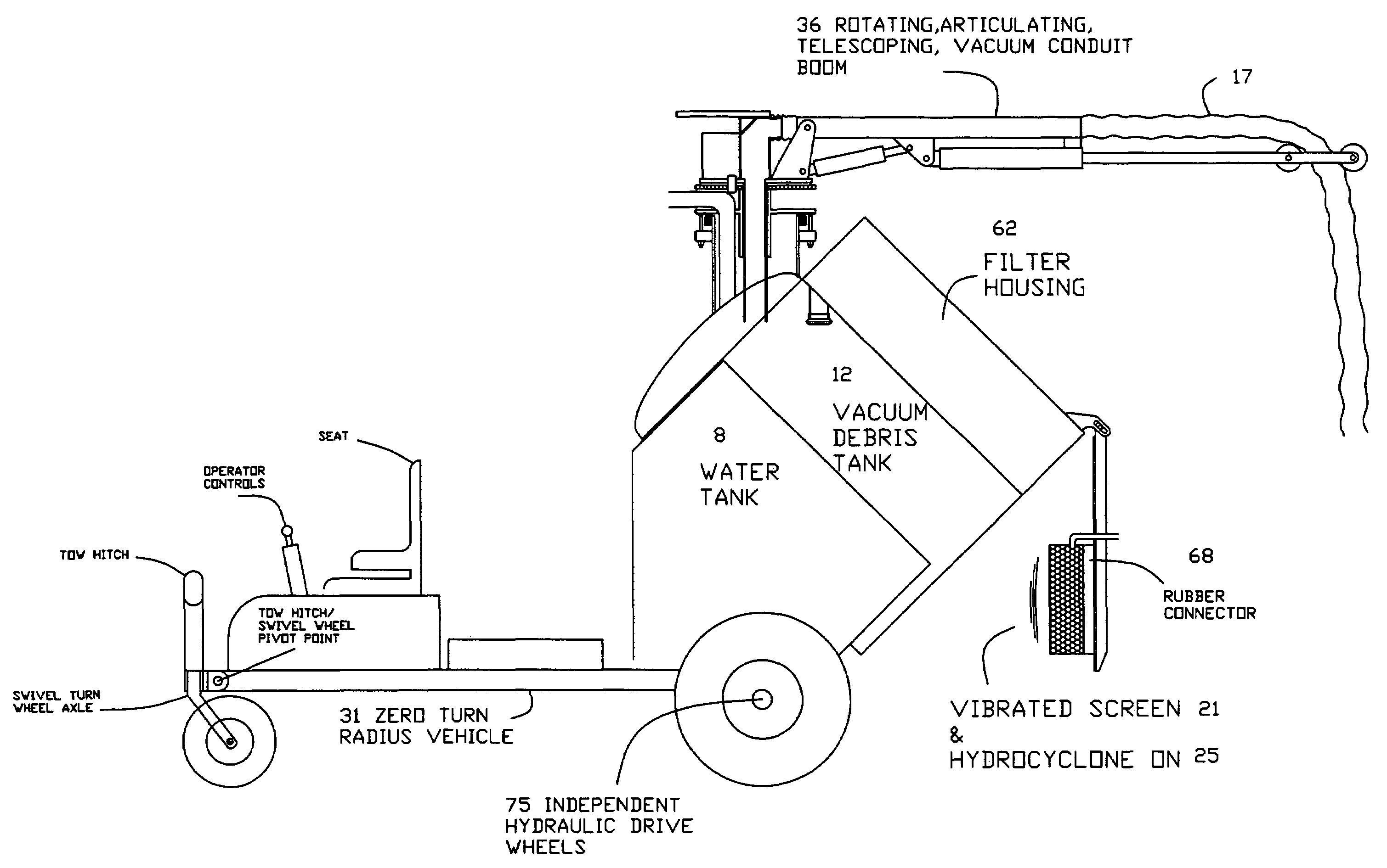
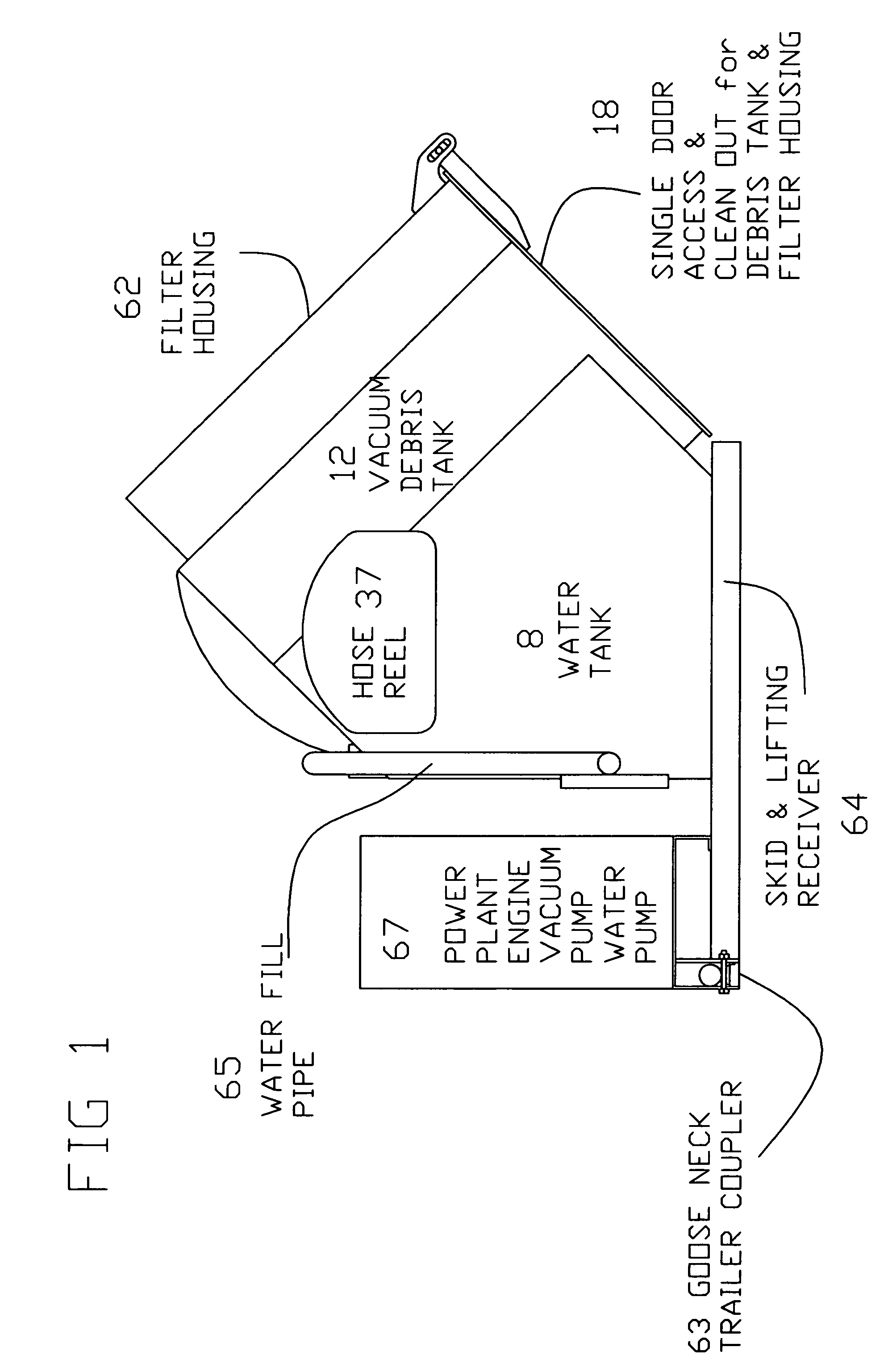
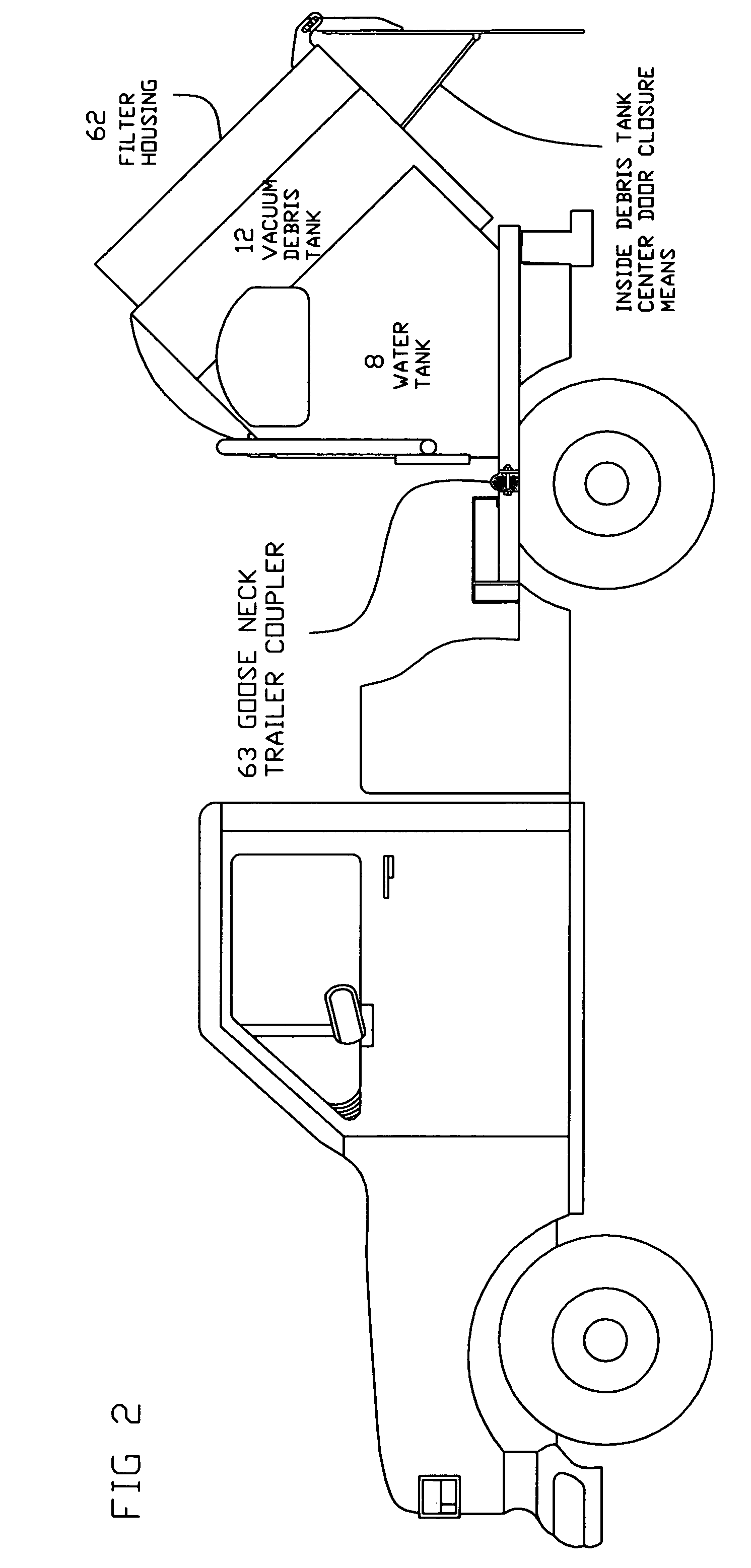
[0044]Referring to FIG. 1, a vacuum container (12) is mounted at a fixed slope and supported by a liquid water container (8). The fixed slope may be of sufficient angle to allow debris to empty by gravity when the access door (18) is opened. This arrangement creates a compact package unit, reduces floor space needed to contain both liquid container (8) and vacuum debris container (12) and condenses the weight of the water container (8) and vacuum debris container (12) combination. The dual container combination lends itself, by compactness, to use as a multifunctional convertible unit capable of being quickly converted from a skid mount unit (64) to a trailer mount unit, to a gooseneck hitch coupled (63) pick up truck bed unit, to a fork lift or skid steer transported unit. A filter housing (62) may be mounted piggyback onto the outer shell of the vacuum debris container (12) thus further compacting the space required for the system and again condensing weight and increasing the eff...


PUM


Abstract

A vacuum container mounted on an inclined slope and having a liquid water storage container mounted beneath the incline of the vacuum container. The water storage container may support the vacuum container. The slope may be of sufficient angle to allow debris to be emptied from the vacuum container by gravity when the access door is opened. A filter housing may be mounted to and supported by the vacuum container. By flush mounting the clean out end of the filter housing with the clean out end of the vacuum container, a single access clean out door may be used to access both simultaneously.

Description

[0001]This application is a CIP of Ser. No. 10 / 217,055, filed Aug. 12, 2002, now U.S. Pat. No. 6,988,568, which is a CIP of Ser. No. 09 / 722,797, filed Nov. 27, 2000, now U.S. Pat. No. 6,453,584, which claims benefit of Ser. No. 60 / 363,058 filed Mar. 11, 2002 and claims benefit of Ser. No. 60 / 384,719 filed Jun. 3, 2002.FIELD OF THE INVENTION[0002]The present invention relates to a vacuum boring and mud recovery container.BACKGROUND OF THE INVENTION[0003]Current state of the art vacuum boring and mud recovery systems, such as U.S. Pat. No. 6,453,584 by the present inventor, have a vacuum container having a vacuum capable of boring and mud recovery and provide simultaneously, vacuum fill, store and dispense. However problems arise from the horizontally mounted debris tank when trying to dispose of the debris.[0004]The primary objective of the present invention is to provide a vacuum boring and mud recovery container having a fixed slope to allow a greater percentage of fill of the debr...

Claims


Application Information

Patent Timeline
Patent Type & Authority Patents(United States)
IPC IPC(8): E02F3/88B63C7/22E01H1/08E01H1/10E02F3/92E02F5/28E02F7/06E03F7/10E03F9/00
CPCE01H1/0827E01H1/103E02F3/8825E02F3/9206E02F5/28E02F7/06E03F7/10E03F9/002
Inventor BUCKNER, LYNN A.
Owner BUCKNER LYNN A
Why Eureka
Try Eureka