Mucus slurping endotracheal tube

a technology of endotracheal tubes and mucus, which is applied in the field of cleaning medical devices, can solve the problems of accumulation of mucus on the inside walls of endotracheal tubes, inability to carry mucus, and inability to maintain a sufficient flow of oxygen to the body, and achieves the effect of greater assurance of cleanliness

Active Publication Date: 2009-03-17
UNITED STATES OF AMERICA
View PDF50 Cites 77 Cited by
  • Summary
  • Abstract
  • Description
  • Claims
  • Application Information

AI Technical Summary

Benefits of technology

[0010]The present invention provides a suctioning assembly built into an endotracheal tube which removes mucus before it accumulates on the inside walls of the endotracheal tube. In the preferred embodiment, one or more suctioning tubes are formed into the walls of an endotracheal tube so that they extend along the length of the endotracheal tube. A plurality of mucus slurping holes are formed at or near the distal end of the endotracheal tube and connected to the suctioning tube(s). When a single suctioning tube is formed in the endotracheal tube walls, the mucus slurping holes are preferably formed at the distal end of a cap which is fused onto the distal end of the endotracheal tube. An annular space is left between the distal end of the cap and the distal end of the endotracheal tube so that the endotracheal tube suction tube can create suction throughout all of the cap's mucus slurping holes. When multiple suctioning tubes are formed in the endotracheal tube walls, each of those suctioning tubes preferably connects to a single corresponding slurping hole at the distal end of the endotracheal tube. In this multiple suctioning tube embodiment, there is no need to fit a cap onto the distal end of the endotracheal tube.
[0012]While the mucus slurper of the present invention has been found to be effective at keeping the inner walls of the endotracheal tube free of mucus deposits, it can nonetheless be combined with other cleaning and disinfectant techniques for greater assurance of cleanliness. For example, the mucus shaver described in co-pending patent application Ser. No. 10 / 773,570 can be periodically used to remove any mucus deposits which might somehow evade the mucus slurper. Also, the inside walls of the endotracheal tube can be coated with a bactericidal film to kill any potentially harmful bacteria which comes into contact with those inside walls.

Problems solved by technology

Through injury or diseases, human or animal lungs can become too weak to sustain a sufficient flow of oxygen to the body and to remove adequate amounts of expired carbon dioxide.
One problem commonly associated with the use of endotracheal tubes is the accumulation of mucus on the inside walls of the endotracheal tube.
This mucus transport mechanism is generally not available, though, to a patient intubated with an endotracheal tube.
If such mucus collection is allowed to continue, the internal diameter of the endotracheal tube will become smaller, which makes it more difficult to breathe.
Needless to say, removing the mucus laden endotracheal tube is very uncomfortable for patient, particularly since ventilation must be interrupted during the removal process.
Moreover, reinsertion of a clean endotracheal tube can lead to tracheal injury, particularly if it is done frequently.
First of all, the suctioning process typically takes 10 to 15 seconds to complete, which can seem like an agonizingly long time for many patients.
Secondly, the suction catheter tends to miss a number of the accumulated mucus deposits and thereby leaves them as a breeding ground for infectious bacteria.

Method used


Image

  • Mucus slurping endotracheal tube
  • Mucus slurping endotracheal tube
  • Mucus slurping endotracheal tube

Examples


example i

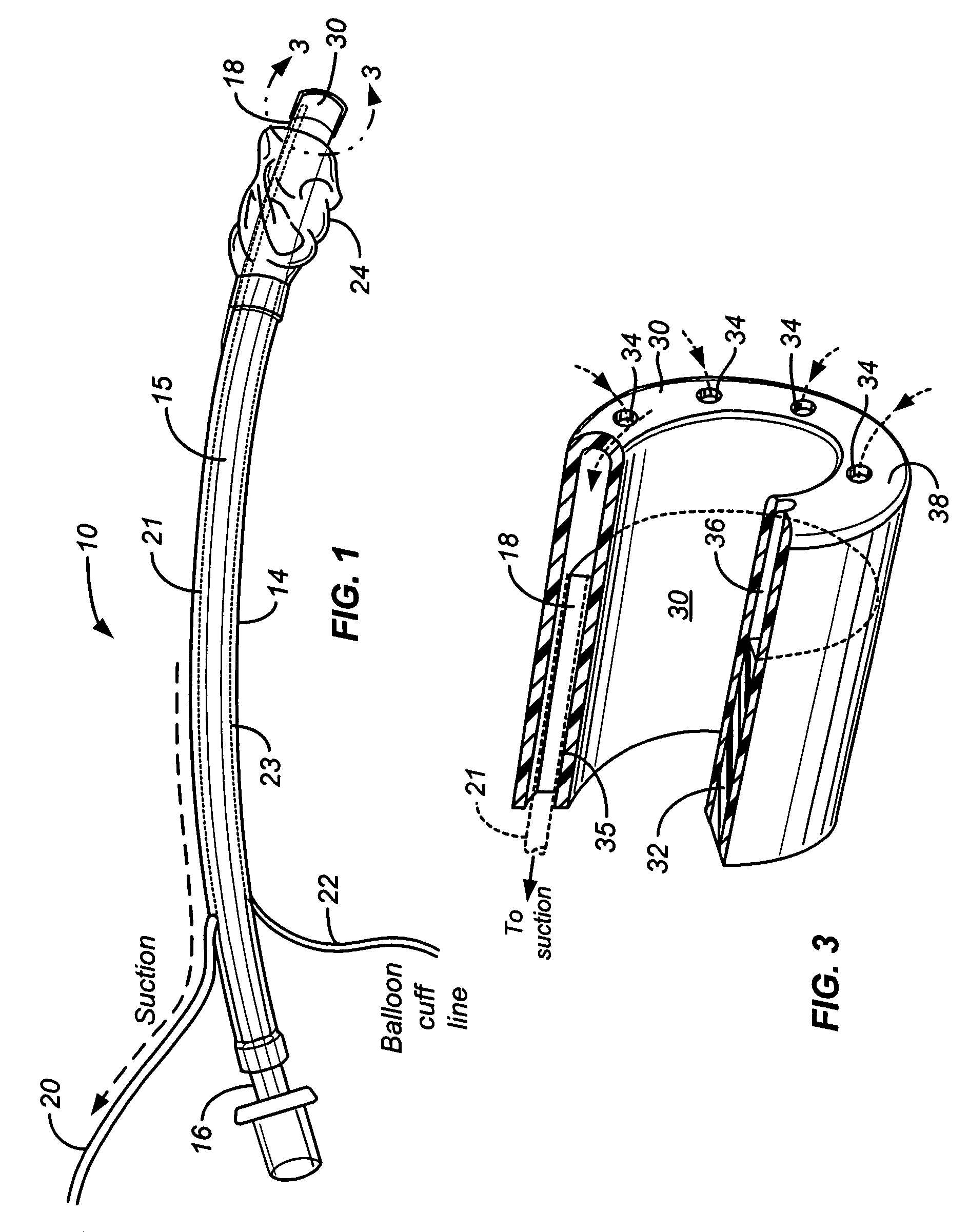
[0031]The mucus slurping endotracheal tube of the present invention was tested with healthy, anesthetized and paralyzed sheep. A Mallinckrodt CASS tube was modified and fitted with a mucus slurping cap in the manner illustrated in FIG. 1 and then inserted into the trachea of the anesthetized sheep. The anesthetized sheep were mechanically ventilated for 72 hours with mucus periodically being suctioned through the mucus slurping cap. No other device was used to assist in the cleaning of mucus from the inside walls of the endotracheal tube. At the end of the 72 hour study, the sheep were euthanized and autopsied.

[0032]After removal and inspection of the modified endotracheal tube, no trace of mucus was found throughout the length of the endotracheal tube. No gross abnormalities of the tracheal mucosa were seen in the autopsied sheep. Bacterial cultures of the 5 lobes of the autopsied sheep lungs were negative. Arterial blood gases were within normal range.


PUM


Abstract

An endotracheal tube assembly (10) is disclosed which suctions away bacteria multiplying mucus before such mucus can accumulate on the inside walls of the endotracheal tube (14). In the preferred embodiment, one or more suctioning tubes (20, 21) are formed into the walls of an endotracheal tube so that they extend along length of the endotracheal tube. A plurality of mucus slurping holes (34) are then formed at or near the distal end of the endotracheal tube and connected to the suctioning tubes. In operation, suctioning through the mucus slurping holes is preferably performed intermittently during patient expiration. By timing this intermittent suctioning with patient expiration, the suctioning flow will be in the same direction as patient breathing. While the mucus slurper of the present invention has been found to be effective at keeping the inner walls of the endotracheal tube free of mucus deposits, it can nonetheless be combined with other cleaning and disinfectant techniques for greater assurance of cleanliness.

Description

TECHNICAL FIELD OF THE INVENTION[0001]The present invention relates to the cleaning of medical devices used to assist breathing. More particularly, mucus slurping holes are formed at or near the distal end of an endotracheal tube to evacuate mucus before it can migrate up onto the inner walls of the endotracheal tube.BACKGROUND OF THE INVENTION[0002]Through injury or diseases, human or animal lungs can become too weak to sustain a sufficient flow of oxygen to the body and to remove adequate amounts of expired carbon dioxide. Under these circumstances, it is often necessary to aid the lungs through forms of mechanical assistance, such as mechanical ventilation.[0003]In a common form, mechanical ventilation involves the introduction of an endotracheal tube and, in some cases, a small, open-ended catheter within that tube, into the trachea of a human or animal. The distal ends of the endotracheal tube and / or catheter are positioned to rest at or slightly above the carina of the lungs. ...

Claims


Application Information

Patent Timeline
Patent Type & Authority Patents(United States)
IPC IPC(8): A61M16/00A62B9/06
CPCA61M16/0463A61M16/0484A61M2016/0027
Inventor KOLOBOW, THEODORBASSI, GIANLUIGI LICURTO, FRANCESCO
Owner UNITED STATES OF AMERICA
Why Eureka
Try Eureka