Liftgate frame

a frame and liftgate technology, applied in the field of liftgates, can solve the problems of limiting the visibility through the rear opening, affecting the operation of the liftgate,

Active Publication Date: 2009-03-17
MAGNA INTERNATIONAL INC
View PDF14 Cites 22 Cited by
  • Summary
  • Abstract
  • Description
  • Claims
  • Application Information

AI Technical Summary

Problems solved by technology

Consequently, the liftgate can be large and heavy, making it difficult for some individuals to open and close the liftgate.
Existing liftgates are typically two-piece, stamped metal components having inner and outer stampings, which restricts visibility through the rear opening.

Method used


Image

  • Liftgate frame
  • Liftgate frame
  • Liftgate frame

Examples


Embodiment Construction

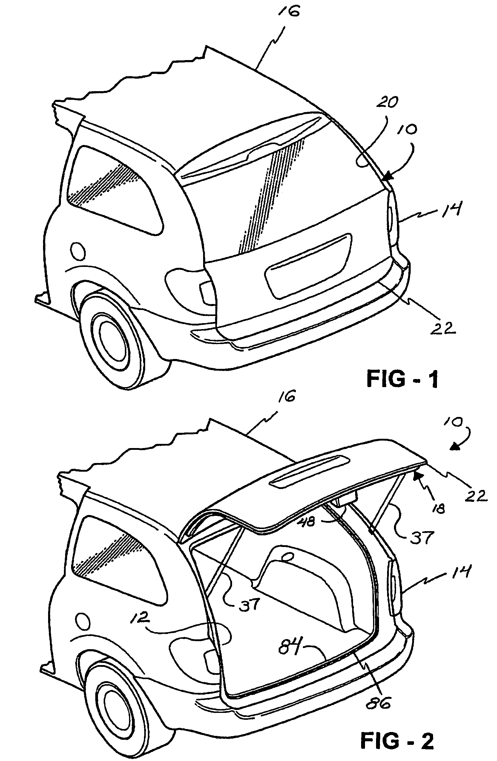
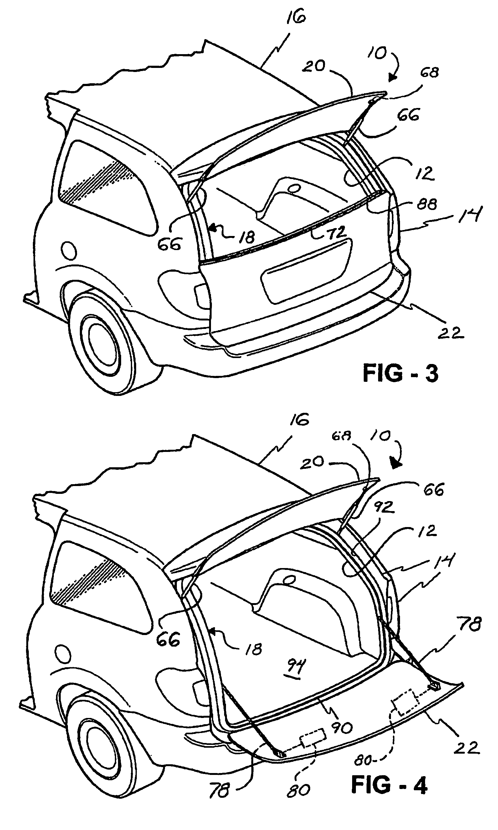
[0018]Referring to FIGS. 1 through 4, a liftgate, generally shown at 10, selectively covers an opening 12 along a rear portion 14 of a motor vehicle 16. The liftgate 10 includes a liftgate frame, generally indicated at 18, which is adapted to be pivotally secured to the motor vehicle 16. The liftgate 10 also includes a window or flipglass 20 pivotally hinged to and supported by the frame 18. The liftgate 10 further includes a tailgate 22, which is also pivotally hinged to and supported by the frame 18. The various pivoting elements allow the liftgate 10 to move between a closed position (FIG. 1), an open position (FIG. 2), a window open position (FIG. 3), and a tailgate open position (FIG. 4). It is appreciated that the various pivoting elements may be manually or power operated.

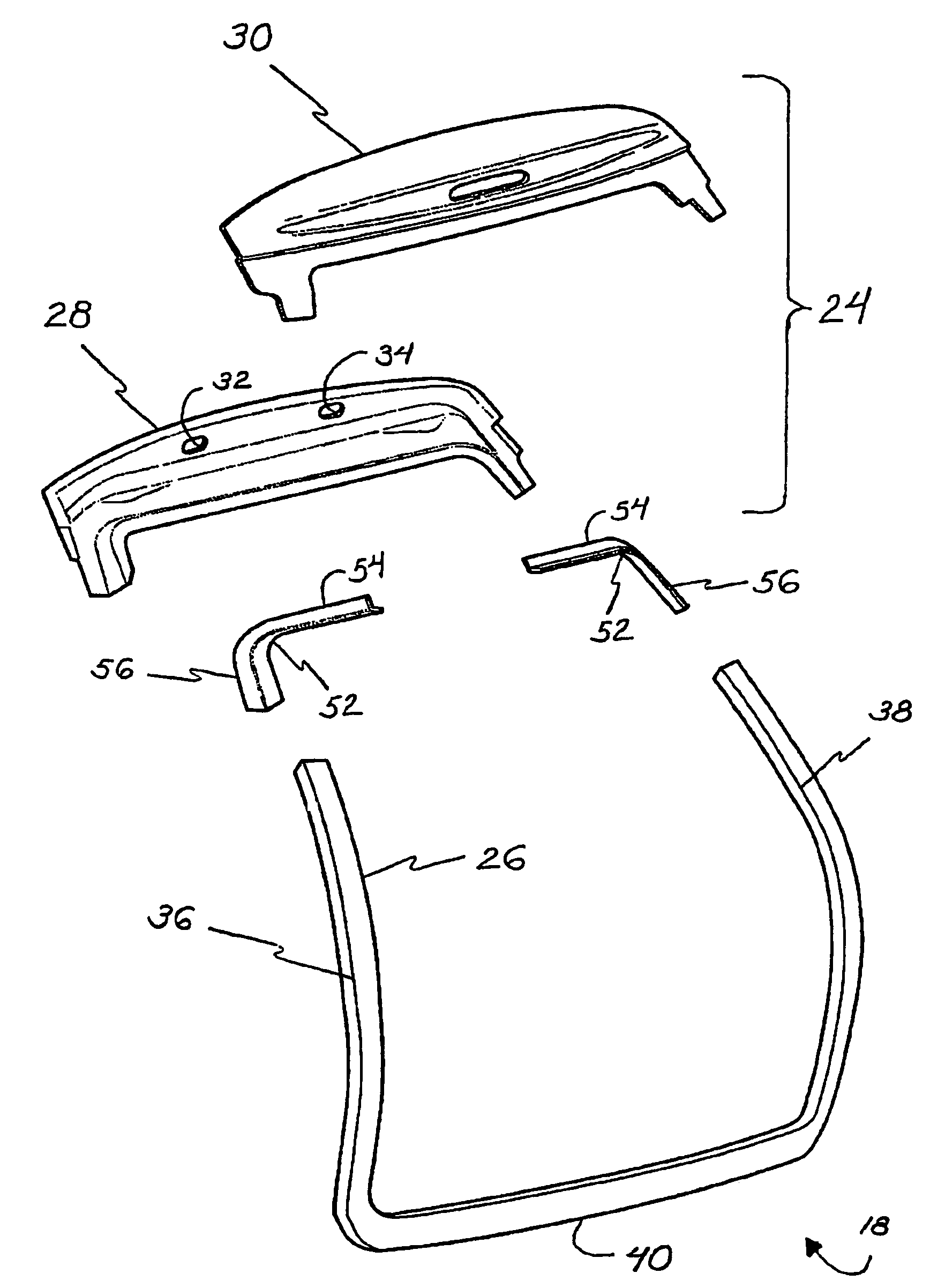
[0019]Referring to FIGS. 5 and 6, the frame 18 includes an upper frame member or header, generally shown at 24, and a generally U-shaped lower frame member 26. The upper frame member 24 extends across the re...


PUM


Abstract

A frame (18) for a liftgate (10) of a motor vehicle includes an upper frame member (24) and a generally U-shaped lower frame member (26). The upper frame member is adapted to be pivotally secured (33, 35) to the motor vehicle. The lower frame member (26) is fixedly secured to the upper frame member (24). The lower frame member (26) is integrally formed, and includes spaced apart vertical segments (36, 38) and a horizontal segment (40) extending therebetween for supporting the liftgate as the liftgate opens and closes.

Description

[0001]This application claims priority from U.S. Provisional Patent Application 60 / 513,653 filed Oct. 23, 2003, the entirety of which is incorporated herein by reference thereto.BACKGROUND OF THE INVENTION[0002]1. Field of the Invention[0003]This invention relates to a liftgate of a motor vehicle. More particularly, the invention relates to a liftgate frame adapted to provide support for a liftgate through multiple opening positions.[0004]2. Description of the Related Art[0005]Certain motor vehicles, including station wagons, sport utility vehicles, and minivans, have a rear opening through which access to an interior of the motor vehicle is gained. The rear opening extends between a floor and a roof of the motor vehicle to allow for loading and unloading of items. Typically, a liftgate is pivotally secured to the motor vehicle to selectively cover the rear opening. To fully cover the rear opening, the liftgate must extend between the floor and the roof of the motor vehicle. Consequ...

Claims


Application Information

Patent Timeline
Patent Type & Authority Patents(United States)
IPC IPC(8): B60J5/10B60J1/18
CPCB60J1/1884B60J5/104B60J5/107B62D25/12
Inventor WERNER, MARK F.
Owner MAGNA INTERNATIONAL INC
Why Eureka
Try Eureka