Method of removing particulates from a printhead using film transfer

a film transfer and printhead technology, applied in printing, other printing apparatus, etc., can solve the problems of slow print speed of all commercially available inkjet printers, printhead failure, and particulates, which are a particular problem in high-speed pagewidth printing, so as to avoid sealing the cavity, avoid the effect of undesirable sealing the cavity and avoid the effect of printhead damage during maintenan

Active Publication Date: 2009-03-24
SILVERBROOK RES PTY LTD +1
View PDF9 Cites 1 Cited by
  • Summary
  • Abstract
  • Description
  • Claims
  • Application Information

AI Technical Summary

Benefits of technology

[0038]The maintenance assembly and method of the present application advantageously allow particulates to be removed from a printhead, whilst avoiding contact of the printhead with an external cleaning device. Hence, unlike prior art squeegee-cleaning methods, the unique cleaning action of the present invention does not impart any shear forces across the printhead and does not damage sensitive nozzle structures. Moreover, the film in the present invention, which does not come into contact with the printhead, is not damaged by the printhead and can therefore be used repeatedly whilst maintaining optimal cleaning action.
[0039]A further advantage of the maintenance assembly is that it has a simple design, which can be manufactured at low cost and consumes very little power. The suction devices of the prior art require external pumps, which add significantly to the cost and power consumption of prior art printers. By obviating the need for a vacuum pump, the power requirements of the printer are significantly reduced.
[0042]Optionally, the film guide is positioned along a first longitudinal edge portion of the printhead. Typically, inkjet printheads (comprised of one or more abutting printhead integrated circuits) have encapsulated wire bonds extending from a longitudinal edge portion. The encapsulant material may be used in the present invention as the film guide. Usually, the encapsulant is a solid polymeric material, which protects the wire bonds from ink and prevents shorting.
[0053]Typically, the ink reservoir comprises one or more ink bags, which can be pressurized by, for example, mechanically squeezing or using a pressurized ink bag container. Optionally, the pressure system comprises a control system for controlling an amount and / or a period of pressure applied to the ink reservoir. For example, the control system may be used to deliver a short burst of positive pressure in order to flood the face for cleaning. However, in a printing mode, it is generally desirable to maintain a slight negative pressure in the air bags in order to counterpoise the capillary draw from the nozzles and prevent ink from flooding across the ink ejection face uncontrollably. The control system may be used to actively control pressure in the air bags for cleaning and / or printing.
[0055]Optionally, the print media guide is moveable between a media-guiding position and a retracted position. In its retracted position, the print media guide allows the film to be fed through the transfer zone and, moreover, avoids sealing the cavity by the film contacting with the print media guide. Alternatively, undesirable sealing of the cavity may be avoided by having vents in the print media guide. Vents may take the form of recesses or openings in the print media guide, which allow pressure in the cavity to be equalized during removal of ink by the film.
[0056]The invention has been developed primarily for use with a MEMS pagewidth inkjet printhead. However, the invention is equally applicable to any type of printhead where remedial measures are required to maintain the printhead in an operable condition. For example, the invention may be used in connection with standard scanning inkjet printheads in order to avoid printhead damage during maintenance.

Problems solved by technology

However, all commercially available inkjet printers suffer from slow print speeds, because the printhead must scan across a stationary sheet of paper.
Printhead failure may be caused by, for example, printhead face flooding, dried-up nozzles (due to evaporation of water from the nozzles—a phenomenon known in the art as decap), or particulates fouling nozzles.
Particulates, in the form of paper dust, are a particular problem in high-speed pagewidth printing.
Frictional contact of the paper with the paper guide generates large quantities of paper dust compared to traditional scanning inkjet printheads, where paper is fed much more slowly.
Hence, pagewidth printheads tend to accumulate paper dust on their ink ejection face during printing.
This accumulation of paper dust is highly undesirable.
Nozzle apertures that are partially covered or blocked produce misdirected ink droplets during printing—the ink droplets are deflected from their intended trajectory by particulates on the ink ejection face.
Misdirects are highly undesirable and may result in acceptably low print quality.
However, whilst sealing / vacuum caps may prevent the ingress of particulates from the atmosphere, such measures do not remove particulates already built up on the printhead.
Moreover, the nozzle plate is typically relatively abrasive due to etched features on its surface.

Method used


Image

  • Method of removing particulates from a printhead using film transfer
  • Method of removing particulates from a printhead using film transfer
  • Method of removing particulates from a printhead using film transfer

Examples


Embodiment Construction

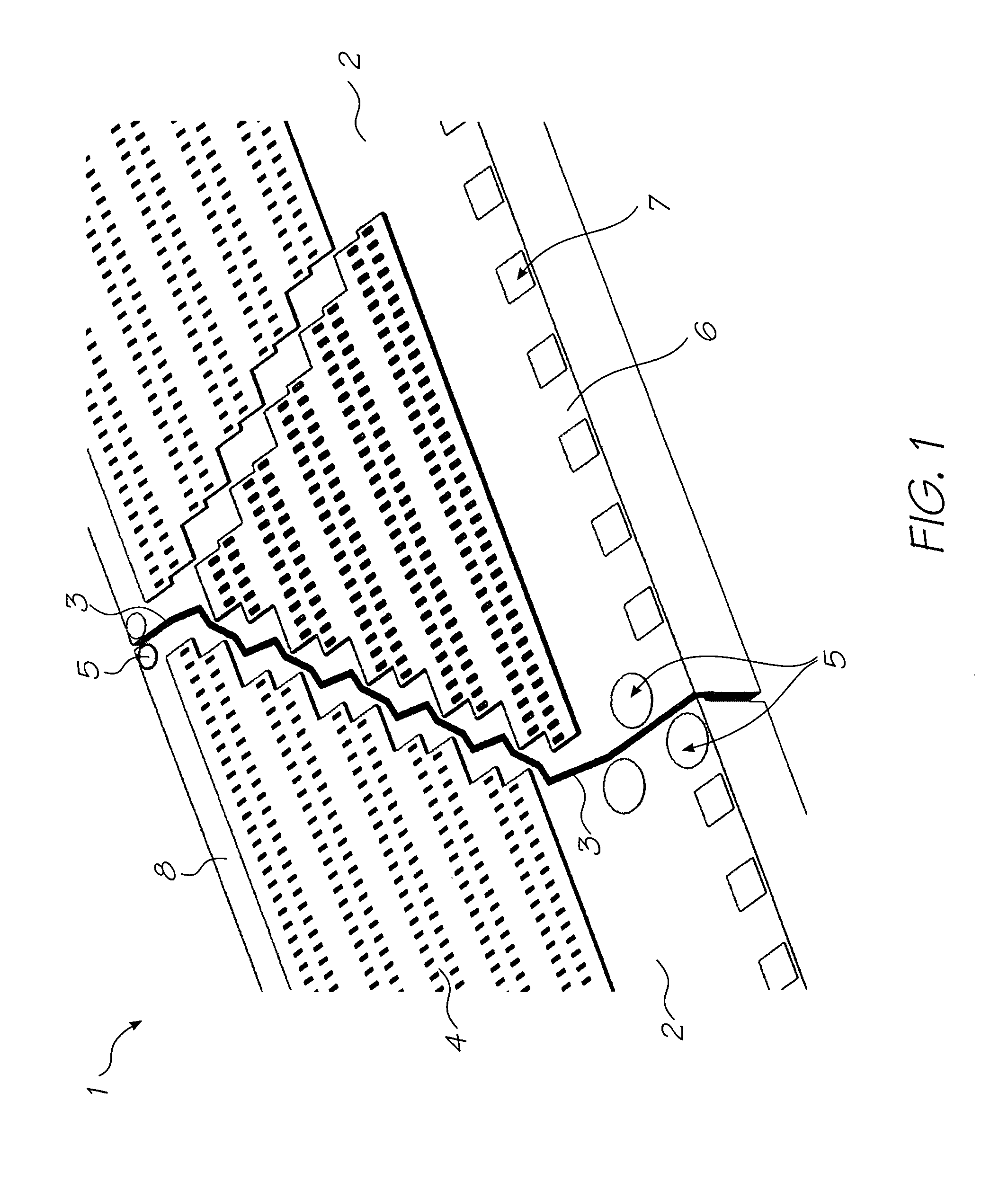
[0265]Referring to FIG. 1, there is shown part of a printhead 1 comprised of aligned printhead integrated circuits 2 abutting along their transverse edges 3. A complete pagewidth printhead (not shown) is formed by an array of printhead integrated circuits 2 abutting across the width of a page. Each printhead integrated circuit 2 comprises rows of nozzles 4, which eject ink onto a print media (not shown) fed past the printhead. Fudicials 5 assist in aligning the array of printhead integrated circuits 2.

[0266]A longitudinal edge portion 6 of the printhead 1 comprises a plurality of bonding pads 7 to which will be attached wire bonds (not shown) in the fully assembled printhead. An opposite longitudinal edge portion 8 of the printhead 1 does not have any bonding pads.

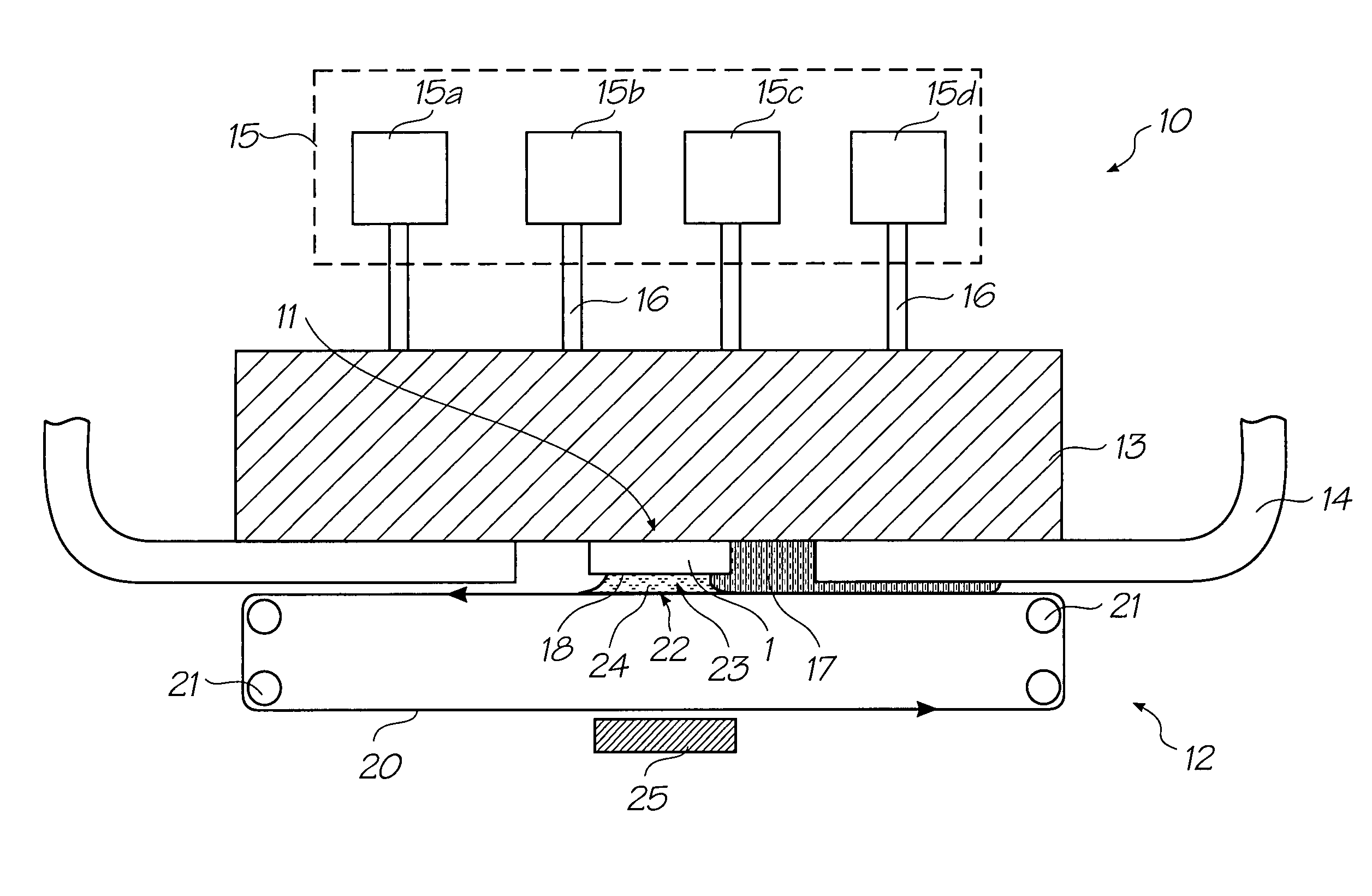
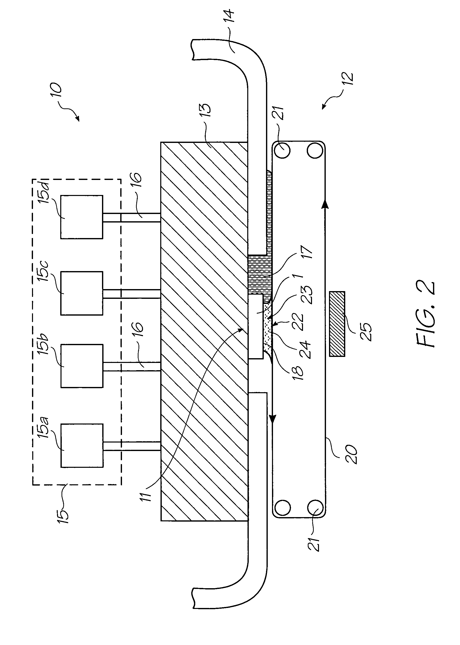
[0267]Referring now to FIG. 2, there is shown a schematic side view of a printhead maintenance assembly 10 comprising a printhead assembly 11 and an ink transport assembly 12. The printhead assembly 11 comprises the printh...


PUM


Abstract

A method of removing particulates from an ink ejection face of a printhead is provided. The method comprises the steps of: (a) flooding the face with ink from the printhead, thereby dispersing the particulates into the flooded ink; and (b) transferring the flooded ink, including the particulates, onto a film moving past the face. Damage to the face is avoided since the film does not contact the face.

Description

CO-PENDING APPLICATIONS[0001]The following applications have been filed by the Applicant simultaneously with the present application:[0002]11 / 24667611 / 24667711 / 24667811 / 24667911 / 24668011 / 24668111 / 24671411 / 24671311 / 24668911 / 24667111 / 24667011 / 24666911 / 24670411 / 24671011 / 24668811 / 24671611 / 24671511 / 24670711 / 24670611 / 24670511 / 24669311 / 24669211 / 24669611 / 24669511 / 24669411 / 24668711 / 246718732268111 / 24668611 / 24670311 / 24669111 / 24671111 / 24669011 / 24671211 / 24671711 / 24670911 / 24670011 / 24670111 / 24670211 / 24666811 / 24669711 / 24669811 / 24669911 / 24667511 / 24667411 / 246667730393011 / 24667211 / 24667311 / 24668311 / 246682[0003]The disclosures of these co-pending applications are incorporated herein by reference.CROSS REFERENCES TO RELATED APPLICATIONS[0004]Various methods, systems and apparatus relating to the present invention are disclosed in the following U.S. patents / patent applications filed by the applicant or assignee of the present invention:[0005]6750901647686367883367249108656685863319466246970644252509 / 517...

Claims


Application Information

Patent Timeline
Patent Type & Authority Patents(United States)
IPC IPC(8): B41J2/165B41J29/38
CPCB41J2/16535B41J2/16552
Inventor KARPPINEN, VESASILVERBROOK, KIA
Owner SILVERBROOK RES PTY LTD
Why Eureka
Try Eureka