Method and device for joining elements to components

a technology of joining elements and components, applied in the direction of soldering apparatus, adhesive processes with surface pretreatment, manufacturing tools, etc., can solve the problems of irregular grain size, affecting the current flow through the arc, and difficult to adapt the joining parameters appropriately

Active Publication Date: 2019-11-14
NEWFREY
View PDF0 Cites 0 Cited by
  • Summary
  • Abstract
  • Description
  • Claims
  • Application Information

AI Technical Summary

Benefits of technology

[0069]The second cleaning effect is a mechanical effect, in which dirt particles are detached and/or carried away by the aerodynamic or kinetic force of the snow jet.
[0070]A third cleaning effect is a ...

Problems solved by technology

Besides, this problem applies if the component and the joining element are each manufactured from an aluminum alloy.
In addition, there may also be problems with regard to irregular grain sizes on the upper layer, which may be up to 1 mm deep, and in particular when using extruded material.
As a result, this may affect the current flow through the arc.
If the coating or the coat comprising such release agents is unevenly distributed over the surface, it is particularly difficult to adapt the joining parameters appropriately.
If coated with carbon, this can lead to pores or cavities in a welded joi...

Method used


Image

  • Method and device for joining elements to components
  • Method and device for joining elements to components
  • Method and device for joining elements to components

Examples


Embodiment Construction

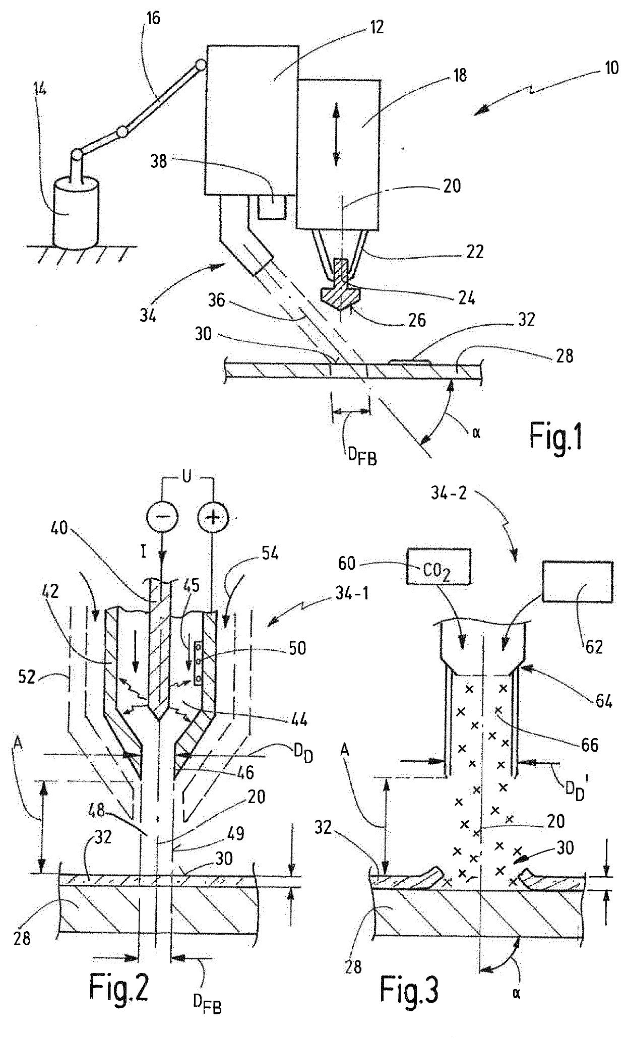
[0097]FIG. 1 is a schematic representation of a joining device for joining joining elements to components, generally referred to as 10.

[0098]The joining device 10 comprises a joining head 12, which can be moved freely in the space by means of a robot 14, said joining head 12 preferably being mounted on one arm 16 of the robot 14 in this case.

[0099]A carriage 18 can preferably be moved along a joining axis 20 on the joining head 12. The maximum stroke of the carriage 18 is preferably larger than a maximum joining stroke.

[0100]A retaining device 22 to retain a joining element 24 is arranged on the carriage 18. The joining element 24 may, for example, be designed as a stud, with a shaft portion which is not shown in greater detail, and a flange portion which is not shown in greater detail, a first joining surface 26 being formed on one side of the flange portion facing away from the shaft portion. The joining element 24 is preferably made from aluminum or aluminum alloy.

[0101]The joini...


PUM

PropertyMeasurementUnit
Lengthaaaaaaaaaa
Lengthaaaaaaaaaa
Electric potential / voltageaaaaaaaaaa

Abstract

A method for joining by welding or gluing joining elements to components, with the following steps: preparation of a joining element, which comprises a first joining surface, and preparation of a component, which comprises a second joining surface; preparation of the first or second joining surface; and carrying out the joining process, in which the joining element is joined to the component; wherein the preparatory step comprises at least one of the following cleaning methods for cleaning the first or second joining surface: a TIG arc method, a plasma gas cleaning method, and a snow jet method.

Description

CROSS-REFERENCE TO RELATED APPLICATIONS[0001]This application is a continuation of international application PCT / EP2017 / 081272, filed Dec. 1, 2017 which claims priority from European Patent Application No. 17178341.8 filed Jun. 28, 2017 and German Patent Application No. 102016125599.8 filed Dec. 23, 2016, the disclosures of which are incorporated herein by reference in their entirety.BACKGROUND OF THE INVENTION[0002]The present invention relates to a method for joining joining elements to components, particularly for stud welding, bolting or gluing with steps including preparing a joining element which comprises a first joining surface, preparing a component which has a second joining surface, preparing said first and / or second joining surface, and carrying out the joining process, in which the joining element is joined to the component, wherein the preparatory step comprises a cleaning method.[0003]The present invention also relates to a joining device for joining a joining element...

Claims


Application Information

Patent Timeline
IPC IPC(8): B23K9/20B23K9/235
CPCB23K9/20B23K9/235B23K1/206B23K11/0053B23K11/34C09J5/02
Inventor EISSARA, BAHMESCHUT, GERSONREIS, CHRISTIAN
Owner NEWFREY
Why Eureka
Try Eureka