Push-in wire connector with improved busbar

a technology of push-in wire connectors and busbars, which is applied in the direction of connection end caps, contact members penetrating/cutting insulation/cable strands, coupling device connections, etc., can solve the problems of inability to withdraw conductors in the opposite direction, and the conductivity between conductors is not good, so as to improve the holding power of spring members

Active Publication Date: 2009-03-24
IDEAL IND INC
View PDF9 Cites 30 Cited by
  • Summary
  • Abstract
  • Description
  • Claims
  • Application Information

AI Technical Summary

Benefits of technology

[0007]The present invention concerns a push-in wire connector having an improved busbar which assists in retaining conductors, including stranded wire, firmly in contact with the busbar.
[0017]These and other objects are realized by a push-in wire connector having a housing and a busbar in the housing. The busbar has a top surface with at least two wire-crossing axes. Each wire-crossing axis intersects at least one of a wire-receiving pocket or a wire-engaging protrusion. In one embodiment, the wire-crossing axis has both the pocket and the protrusion, which together provide a serpentine wire path that enhances the holding power of a spring member.

Problems solved by technology

But even a highly conductive busbar will not provide good conductivity between conductors if those conductors are not held firmly in contact with the busbar.
The spring fingered is angled to permit insertion of the conductor past the finger in one direction but withdrawal of the conductor in the opposite direction is not permitted due to the self-locking configuration of the spring finger.
While firm support for the busbar can be provided either by the spring member or the housing, or both, a problem can arise when the connector is used with stranded wire.

Method used


Image

  • Push-in wire connector with improved busbar
  • Push-in wire connector with improved busbar
  • Push-in wire connector with improved busbar

Examples


Embodiment Construction

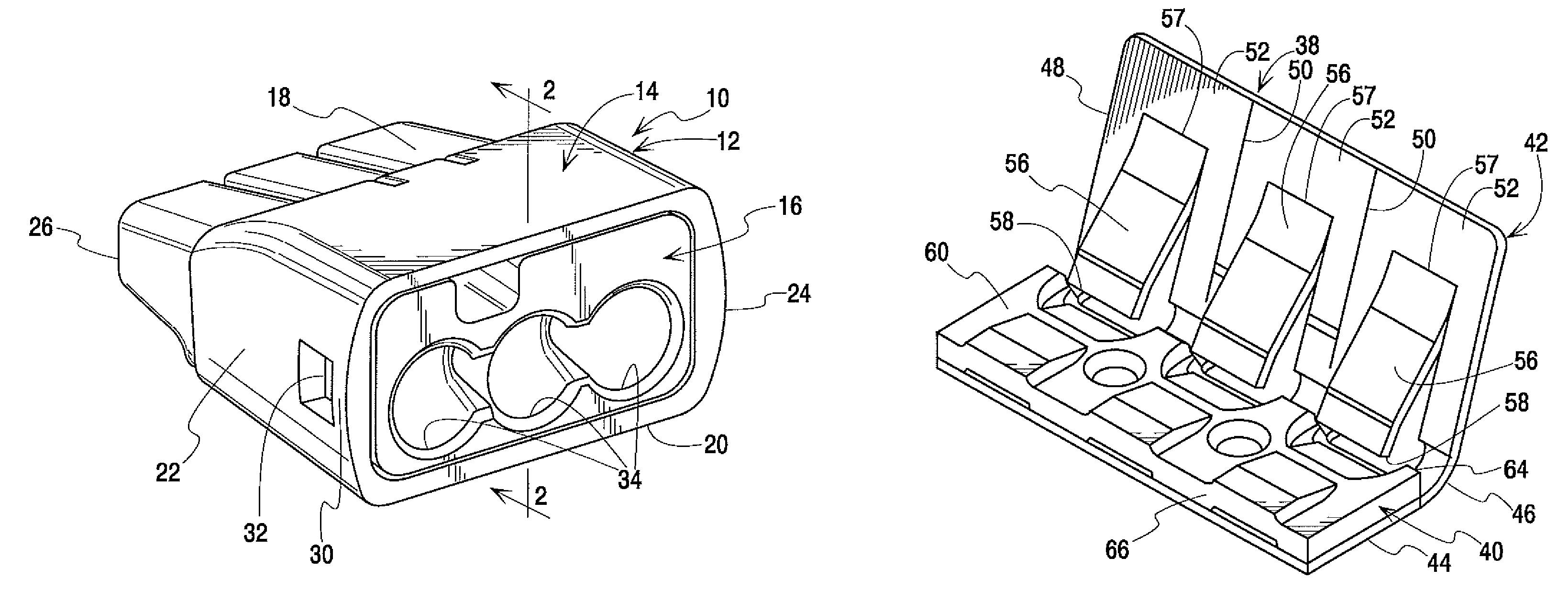
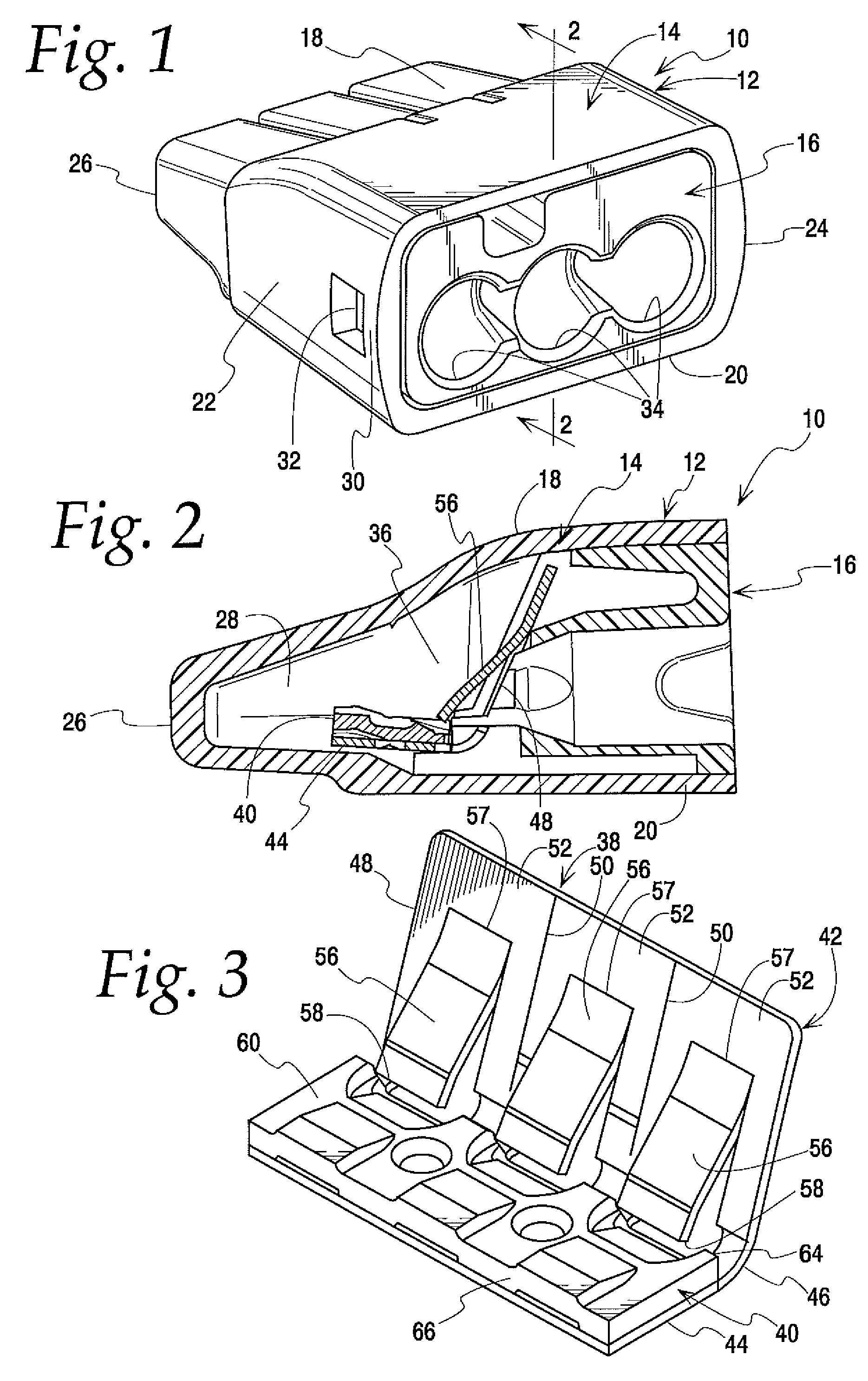
[0032]FIG. 1 illustrates the push-in connector 10 of the present invention. The push-in connector has a housing shown generally at 12. In this embodiment the housing is formed in two pieces and includes a five-sided case 14 and a cap 16. The case has top and bottom walls 18 and 20 joined by left and right side walls 22 and 24. A rear wall 26 closes the back end of the case. Together the case walls define a generally hollow interior 28 of the housing. The front side of the case is open to receive the cap 16. The side walls 22, 24 each have a latch 30, one of which can be seen in FIG. 1. The latches 30 engage hooks 32 which protrude from the sides of the cap to retain the cap 16 in the case 14. As seen in FIGS. 1 and 2, the cap has a plurality of ports 34 therethrough. These ports provide access to the hollow interior 28 of the case. Partitions as at 36 may be provided in the interior of the housing to guide the stripped ends of wires as they are inserted into the housing,

[0033]Turnin...


PUM


Abstract

A push-in wire connector has an improved busbar suitable for use with either solid or stranded wire. The connector has a housing with a hollow interior. At least two openings in the housing provide access to the interior for the ends of wires inserted into the connector. A busbar is mounted in the housing. The busbar defines at least two wire-crossing axes extending from an entry edge to an exit edge and a thickness between a top face and a bottom face. The busbar has a wire-receiving pocket extending below the top face on each of the wire-crossing axes and a wire-engaging protrusion extending above the top face on each of the wire-crossing axes.

Description

BACKGROUND OF THE INVENTION[0001]This invention relates to push-in wire connectors. Push-in connectors operate, as the name implies, by simply pushing a stripped end of two or more wires or conductors into the connector. Once the wires are pushed into the connector no closing, crimping, twisting, insulation displacement or other manipulation of the connector is required to finish the connection, making the push-in connector advantageous from the standpoint of time needed to install it. The push-in connector must perform several tasks including electrically isolating its conductors from the surrounding environment, retaining the conductors in the connector, and providing good electrical conductivity between the conductors.[0002]The electrical isolation function is typically performed by a housing made of electrically insulating material. The housing has a generally hollow interior. Openings in the housing provide access to the interior for the stripped ends of two or more electrical ...

Claims


Application Information

Patent Timeline
Patent Type & Authority Patents(United States)
IPC IPC(8): H01R4/24
CPCH01R4/4818H01R4/22H01R31/085H01R11/09H01R2101/00H01R4/48185
Inventor KESWANI, SUSHIL N.SWEDBERG, BENJAMIN D.
Owner IDEAL IND INC
Why Eureka
Try Eureka