
Caliper

a technology of calipers and calipers, applied in the field of calipers, can solve the problems of time-consuming and troublesome measurement of such calipers, and achieve the effect of accurate size measuremen

Active Publication Date: 2009-03-31
HU BOBBY
View PDF10 Cites 8 Cited by
  • Summary
  • Abstract
  • Description
  • Claims
  • Application Information

AI Technical Summary

Benefits of technology

"The present invention is a caliper that solves the problem of accurately measuring the size of objects. It includes two legs that pivot together, with abutting portions that move towards each other to measure the size of an object. The caliper also has slots and an indicator that moves along the slots to indicate the size of the object. The caliper is easy to use and can quickly measure the size of an object."

Problems solved by technology

The measurement with such a caliper 1 is troublesome and time-consuming.

Method used


Image

  • Caliper
  • Caliper
  • Caliper

Examples


Embodiment Construction

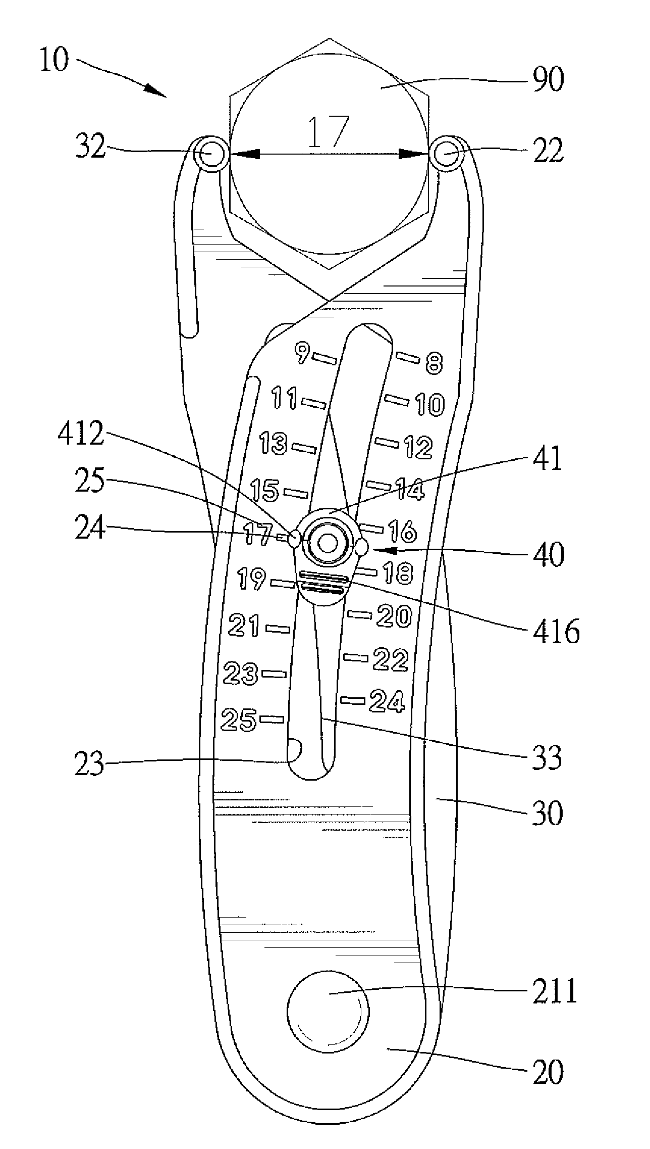
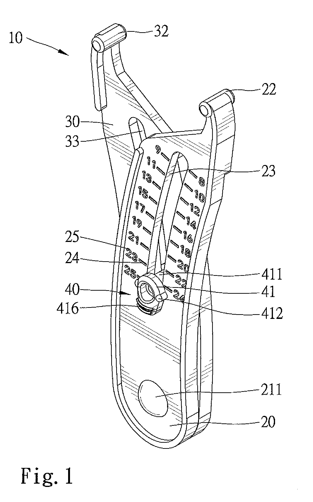
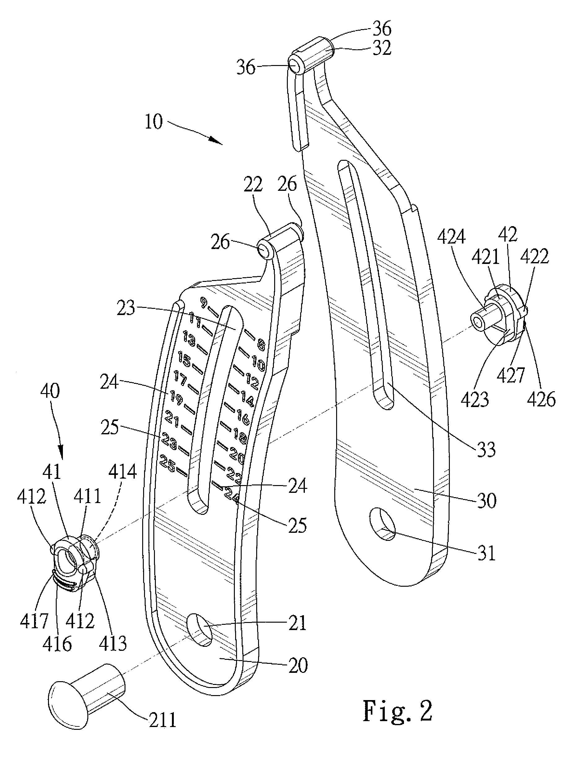
[0019]A caliper according to the preferred teachings of the present invention is shown in FIGS. 1-6 of the drawings and generally designated 10. The caliper 10 can be utilized to rapidly gauge the size of an object such as a nut, bolt head, fitting, etc.

[0020]According to the preferred form shown, the caliper 10 includes a first leg 20 and a second leg 30. The first leg 20 is substantially a blade having a thickness defined between an outer face and an inner face thereof. The first leg 20 includes a first end having a pivot hole 21 extending from the outer face through the inner face of the first leg 20. The first leg 20 further includes a second end having an abutting portion 22. The abutting portion 22 is substantially a cylinder having a longitudinal axis parallel to and extending across the thickness of the first leg 20, with two ends 36 of the cylinder respectively extending beyond the inner and outer faces of the first leg 20. An arcuate slot 23 is defined between and spaced f...


PUM


Abstract

A caliper includes a first leg and a second leg pivotably connected together at first ends thereof. First and second abutting portions are respectively formed on second ends of the first and second legs. First and second slots are respectively defined in the first and second legs and between the first and second ends thereof. An indicator is slideably received in the first and second slots. The indicator is slideable along the first and second slots to move the first and second abutting portions toward each other until the first and the second abutting portions respectively abut against two opposite sides of an object to be gauged by the caliper. The size of the object is indicated by an indicating portion of the indicator that points to a scale on one of the first and second legs.

Description

BACKGROUND OF THE INVENTION[0001]The present invention relates to a caliper and, more particularly, to a caliper for rapidly gauging the size of a nut, bolt head, or fitting.[0002]FIG. 7 of the drawings illustrates a typical caliper 1 for measuring an object 6 such as a nut, bolt head, fitting, etc. The caliper 1 includes two legs 2 pivoted together at an end. A rod 3 has an end extended through an intermediate portion of one of the legs 2 to an intermediate portion of the other leg 2. An adjusting knob 4 is threadedly engaged with a threaded section 5 on the rod 3. In use, the adjusting knob 4 is rotated until outer ends of the legs 2 come in contact with two opposite sides of an object 6. The object 6 is then removed, and the size of the object 6 can be known by measuring the distance between the outer ends of the legs 2 with a ruler or the like. The measurement with such a caliper 1 is troublesome and time-consuming.[0003]It is therefore a need for a caliper allowing rapid, relia...

Claims


Application Information

Patent Timeline
Patent Type & Authority Patents(United States)
IPC IPC(8): G01B5/02G01B3/16
CPCG01B3/166
Inventor HU, BOBBY
Owner HU BOBBY
Learn More