Apparatus for integrating a rigid structure into a flexible wall of an inflatable structure

a technology of rigid structure and inflatable structure, which is applied in the direction of cosmonautic vehicles, transportation and packaging, lighter-than-air aircraft, etc., can solve the problems of limited size and configuration of rigid structure, unique challenges for designers, and complications with certain design features

a technology of rigid structure and inflatable structure, which is applied in the direction of cosmonautic vehicles, transportation and packaging, lighter-than-air aircraft, etc., can solve the problems of limited size and configuration of rigid structure, unique challenges for designers, and complications with certain design features

US7509774B1Inactive Publication Date: 2009-03-31NASA

Image

  • Apparatus for integrating a rigid structure into a flexible wall of an inflatable structure
  • Apparatus for integrating a rigid structure into a flexible wall of an inflatable structure
  • Apparatus for integrating a rigid structure into a flexible wall of an inflatable structure

Examples


first embodiment

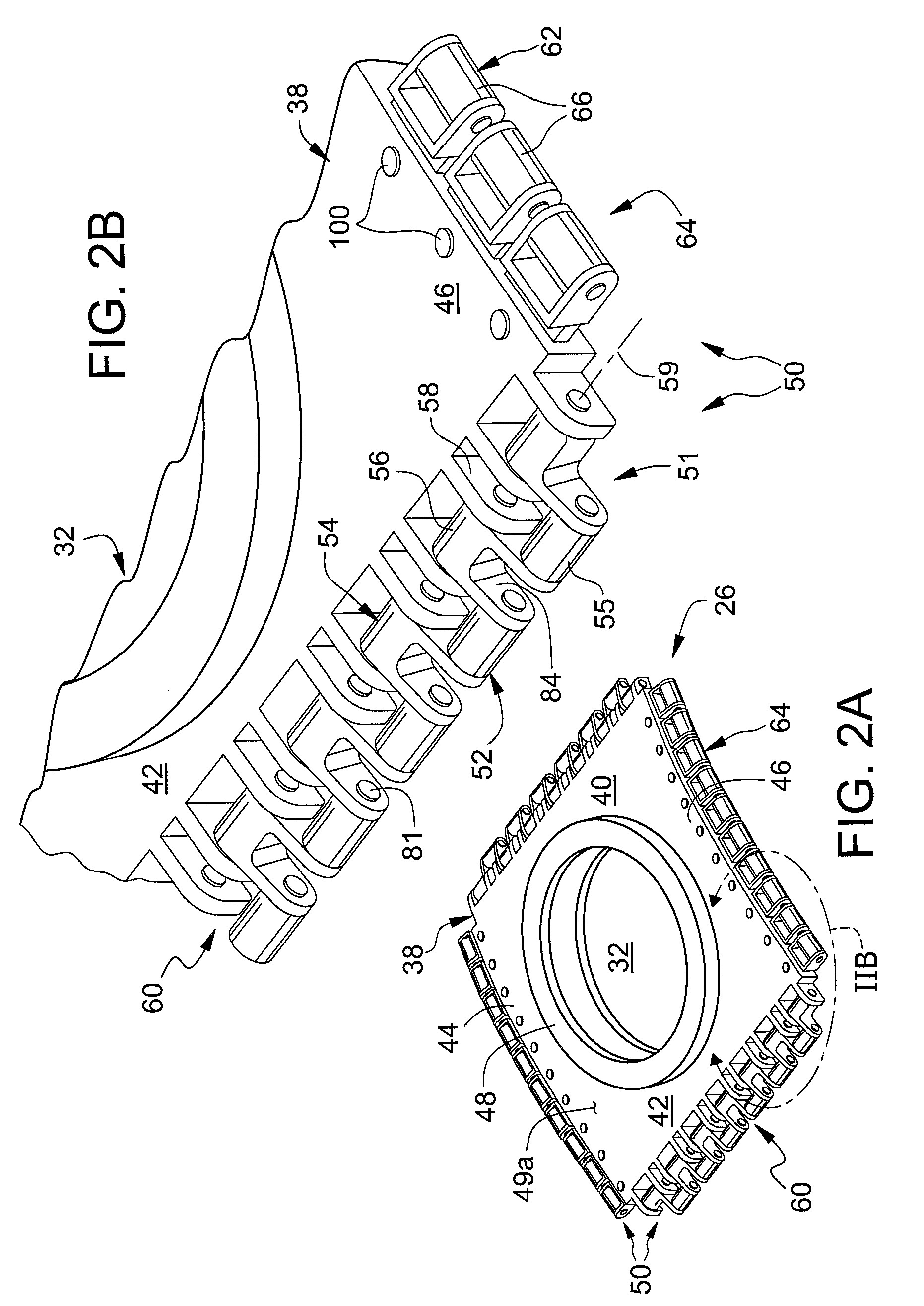
[0083]As disclosed, means are provided for reducing potentially damaging, differential stresses on the respective flexible straps, for ensuring that such forces are evenly distributed, and for accommodating the differing reactions to stress of the rigid and flexible components. For example, such differential stresses are accommodated by the use of connecting mechanisms particularly adapted for connecting the mutually parallel circumferential and mutually parallel longitudinal webbing straps to one or more rigid panel members, such as window frames, such that tensional loads are equally distributed thereon; such that the loads are parallel to the major axes of the panel; and such that bending moments on elements on the panel are reduced. Non-axial stress on the connecting mechanisms, such as the lever effect that could be associated with elongated members supporting roller-bearing devises as previously discussed, are reduced, particularly with respect to the first embodiment incorpor...

second embodiment

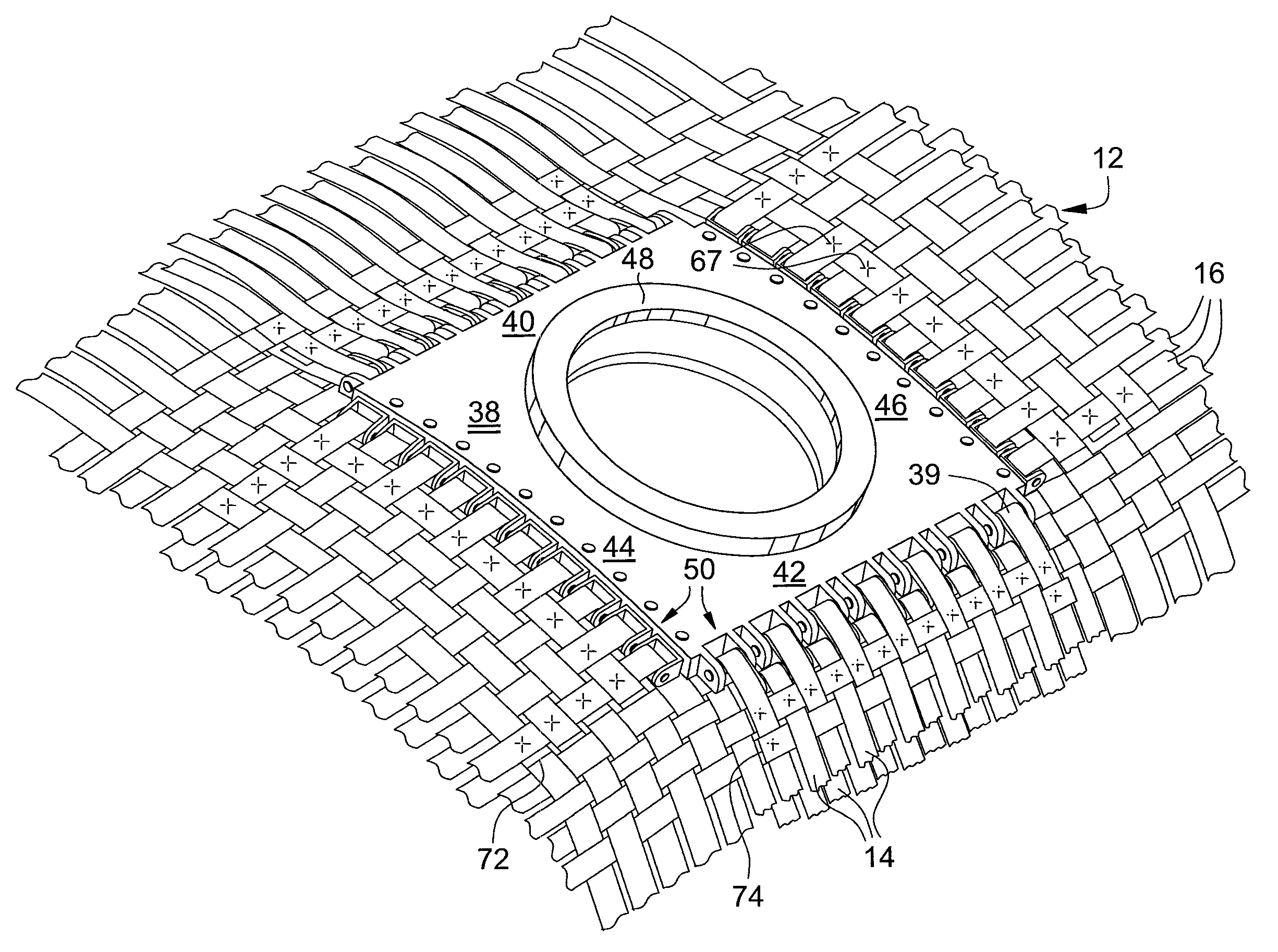
[0085]As will now be understood, the circumferential straps 14 may be positioned in mutually adjacent, mutually contiguous alignment rather than mutually spaced alignment because the staggered array 60 of connecting mechanisms 52, 54, and, in the second embodiment, the staggered array 160 of connecting mechanisms 152 and 154 permit closer spacing of the straps 14. As noted above, this is because the inner connecting mechanisms are positioned behind the outer connecting mechanisms and may therefore extend laterally on either side of the outer connecting mechanisms, permitting their respective rollers to be spaced closer together along the frame end portions 40, 42.

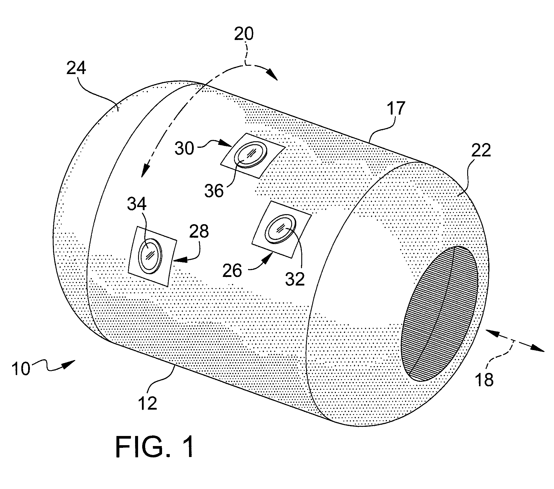
[0086]As discussed in previous sections, tension applied along straps extending circumferentially around the cylindrical, longitudinally extending inflatable module body is normally greater than that applied along straps extending longitudinally, along the length of the elongated body. Accordingly, in some applications, if ...


PUM


Abstract

For an inflatable structure having a flexible outer shell or wall structure having a flexible restraint layer comprising interwoven, load-bearing straps, apparatus for integrating one or more substantially rigid members into the flexible shell. For each rigid member, a corresponding opening is formed through the flexible shell for receiving the rigid member. A plurality of connection devices are mounted on the rigid member for receiving respective ones of the load-bearing straps. In one embodiment, the connection devices comprise inner connecting mechanisms and outer connecting mechanisms, the inner and outer connecting mechanisms being mounted on the substantially rigid structure and spaced along a peripheral edge portion of the structure in an interleafed array in which respective outer connecting mechanisms are interposed between adjacent pairs of inner connecting mechanisms, the outer connecting mechanisms projecting outwardly from the peripheral edge portion of the substantially rigid structure beyond the adjacent inner connecting mechanisms to form a staggered array of connecting mechanisms extending along the panel structure edge portion. In one embodiment, the inner and outer connecting mechanisms form part of an integrated, structure rotatably mounted on the rigid member peripheral edge portion.

Description

ORIGIN OF THE INVENTION[0001]The invention described herein was made by employees of the United States Government and may be manufactured and used by or for the government of the United States of America for governmental purposes without the payment of any royalties thereon or therefore.FIELD OF THE INVENTION[0002]This invention relates generally to inflatable structures having flexible outer walls and, more particularly, to apparatus and methods for integrating rigid structures, such as panels, bulkheads, window frame assemblies, hatches, and the like, into the flexible outer walls of such inflatable structures.BACKGROUND OF THE INVENTION[0003]The use of inflatable structures is of interest for applications in which it is desired to provide storage facilities, habitats, laboratories, or the like in remote or isolated locations. Such an inflatable structure may be conveniently transported to a desired location or region in a reduced-volume, non-inflated mode and deployed at the site...

Claims


Application Information

Patent Timeline
31 Mar 2009
Publication
US7509774B1
IPC
E04G11/04; B64G1/00; B64G1/14
CPC
B64G1/12; B64G1/222; B64G2001/224; B64G1/2227
Inventors
JOHNSON, CHRISTOPHER J.; PATTERSON, ROSS M.