Pyromechanical separating device with a specially shaped current conductor rail

a technology of current conductor rail and separating device, which is applied in the direction of contact mechanism, circuit-breaking switch, tractors, etc., can solve the problem of undesired interruption of current supply in the vehicl

Active Publication Date: 2009-03-31
AUTOLIV DEV AB
View PDF21 Cites 36 Cited by
  • Summary
  • Abstract
  • Description
  • Claims
  • Application Information

AI Technical Summary

Benefits of technology

[0009]Alternatively, one transition has a one-sided notch in the tapering and the other transition is constructed as a bending point. In this way the disconnecting tool can cut through the disconnecting point

Problems solved by technology

A disadvantage of this way of carrying conductors is that, because the conductors are carried in a straight line through the necessary screw connection, e.g. to a car battery, the vibrations, jolts, changes in temperature, etc., occurring during o

Method used


Image

  • Pyromechanical separating device with a specially shaped current conductor rail
  • Pyromechanical separating device with a specially shaped current conductor rail
  • Pyromechanical separating device with a specially shaped current conductor rail

Examples


Embodiment Construction

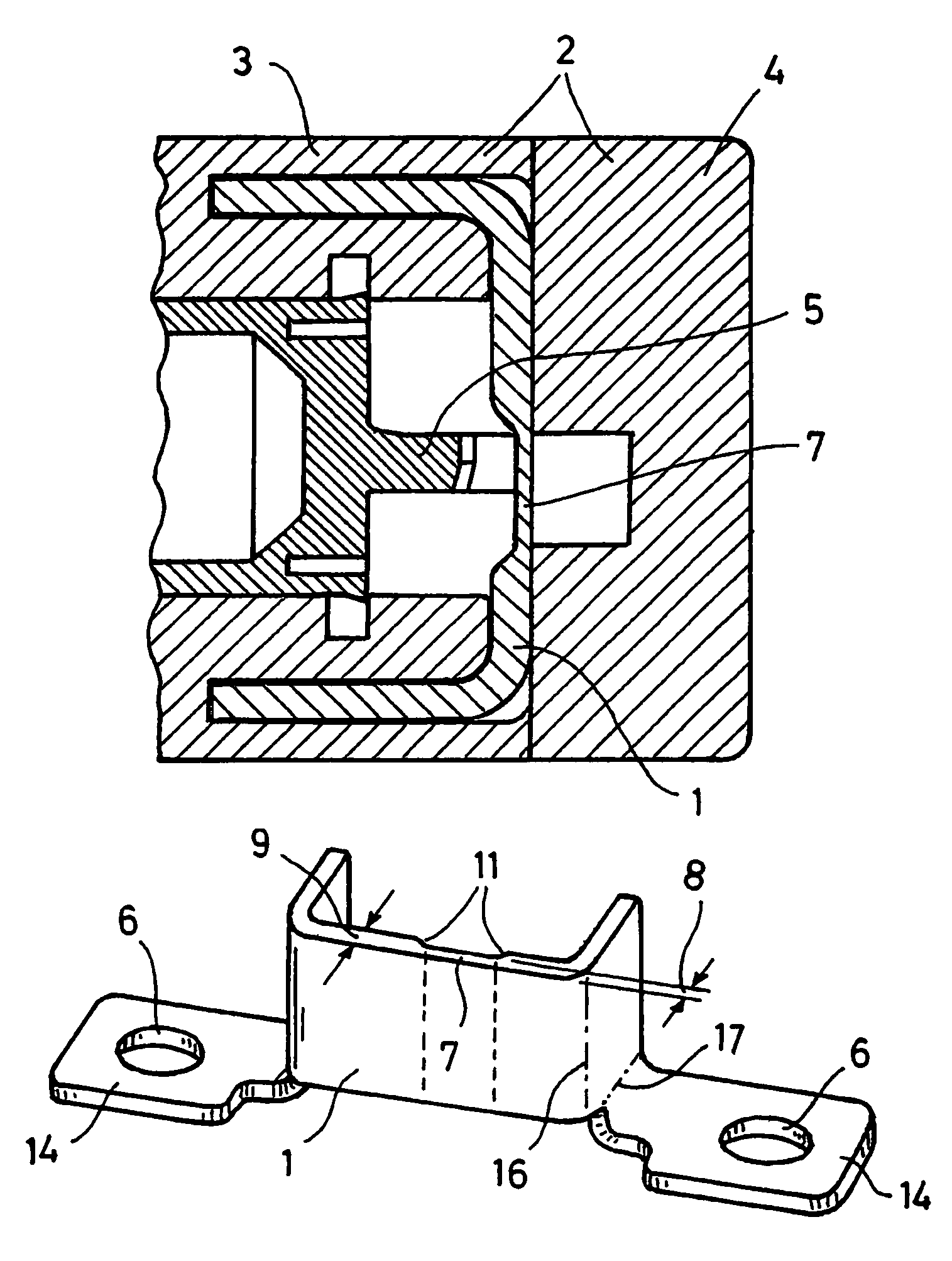
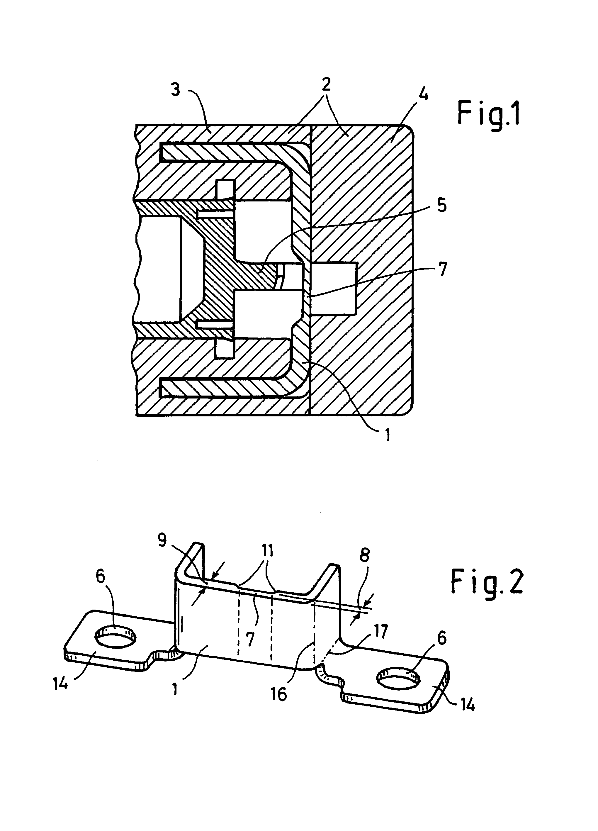
[0018]FIG. 1 illustrates a current conductor rail 1 located in a housing 2 consisting of a housing lower part 3 and a housing upper part 4. Further indicated in FIG. 1 is a disconnecting tool 5 which is accelerated by suitable measures and disconnects the current conductor rail 1 owing to its kinetic energy.

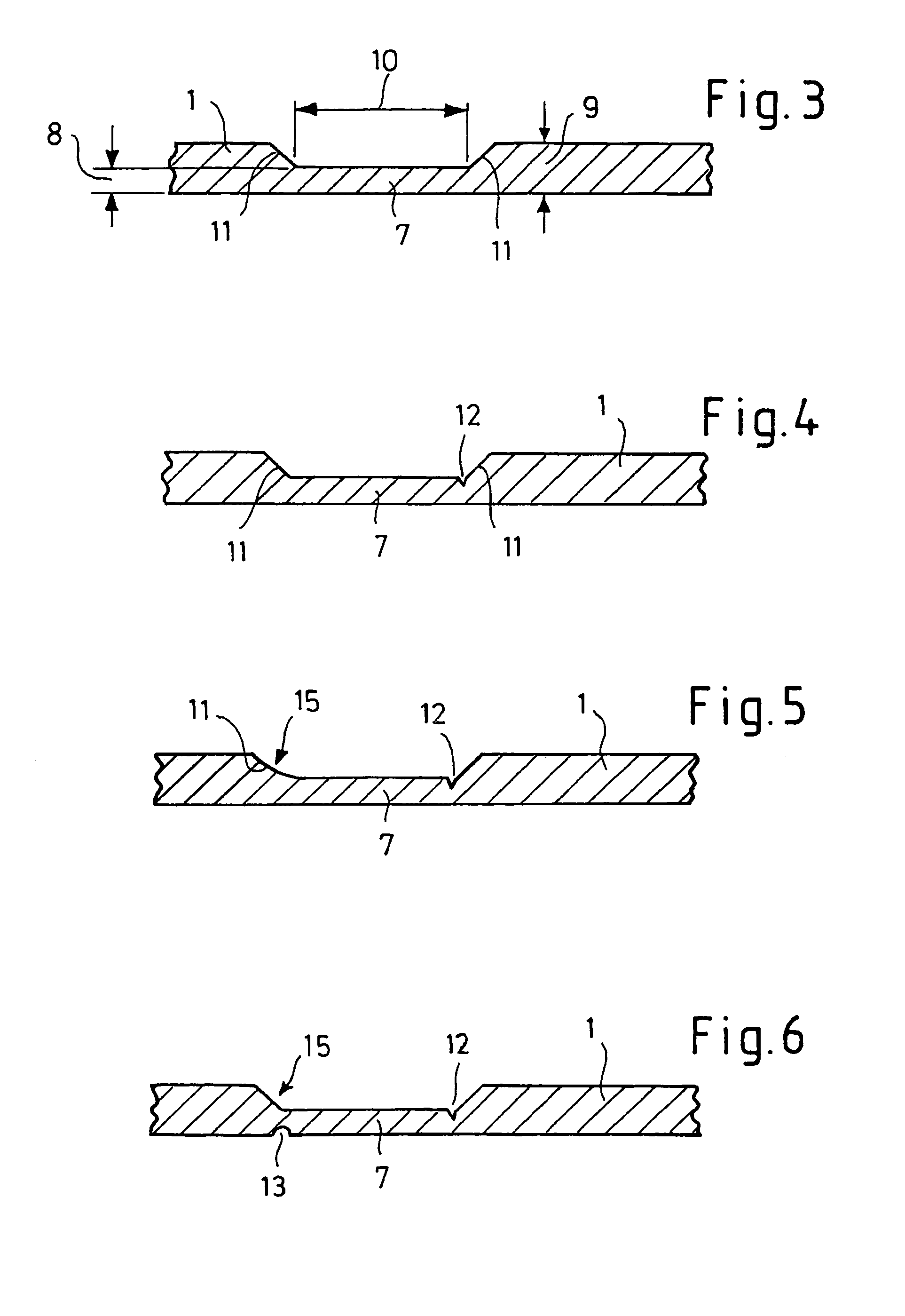
[0019]FIG. 2 shows the current conductor rail 1 as a whole. The disconnecting point 7 forms a quadrangle on the current conductor rail 1 with two transitions 11 to the remaining current conductor rail 9, arranged cross-wise to the longitudinal direction of the current conductor rail 1. On the end pieces 11 (sic) a fastening facility 6, here fastening holes, is arranged in each case. These two end pieces 14 are arranged at right angles to the plane of the disconnecting point 7. This rectangular arrangement to the plane of the disconnecting point 7 is achieved by double rectangular bending of the current conductor rail 1 at two different points 16, 17 in each case. This advantageou...


PUM


Abstract

A pyromechanical disconnecting device having an improved electric current conductor rail. The electric current conductor rail includes a center section perpendicular to the path of a disconnecting tool, and a first and second side section extending perpendicular from the center section. The electric current conductor rail further includes a first and second end piece connected respectively to the first and second side sections apart from the center section. Each of the end pieces is connected along a fold perpendicular to the center section and includes a bore for receiving a fastener to attach the electric current conductor rail to a housing.

Description

TECHNICAL FIELD OF INVENTION[0001]The invention relates to a pyromechanical disconnecting device with a housing in which an electrically conducting current conductor rail is arranged, constructed as able to be cut through by a disconnecting tool driven by a pyrotechnical propellant charge at a disconnecting point, and the current conductor rail has on its end pieces in each case a fastening facility for connecting electrical conductors.BACKGROUND OF THE INVENTION[0002]A pyromechanical disconnecting device of this kind is described in DE 197 12 387 A1 and shows an electrically conducting current conductor rail arranged in a straight line in a housing.[0003]A disadvantage of this way of carrying conductors is that, because the conductors are carried in a straight line through the necessary screw connection, e.g. to a car battery, the vibrations, jolts, changes in temperature, etc., occurring during operation of the vehicle, result in undesired deformations and twisting of the current ...

Claims


Application Information

Patent Timeline
IPC IPC(8): H01H71/20B60K28/10H01H37/76H01H39/00
CPCH01H39/006H01H2039/008
Inventor VON BEHR, DIEDRICHBREDE, UWEKORDEL, GERHARDNEUSER, JUERGENSEITZ, WOLFGANGBAYER, PAULUSSEITZ, GEORG
Owner AUTOLIV DEV AB
Why Eureka
Try Eureka