Model-driven software deployment in an application server

a software deployment and model technology, applied in the field of application deployment, can solve the problems of not addressing the issue of sharing common code, or wha

Inactive Publication Date: 2009-03-31
IBM CORP
View PDF8 Cites 41 Cited by
  • Summary
  • Abstract
  • Description
  • Claims
  • Application Information

AI Technical Summary

Problems solved by technology

This statement, however, does not address the issue of the sharing of common code, or what are often referred to as dependent libraries.

Method used


Image

  • Model-driven software deployment in an application server
  • Model-driven software deployment in an application server
  • Model-driven software deployment in an application server

Examples


Embodiment Construction

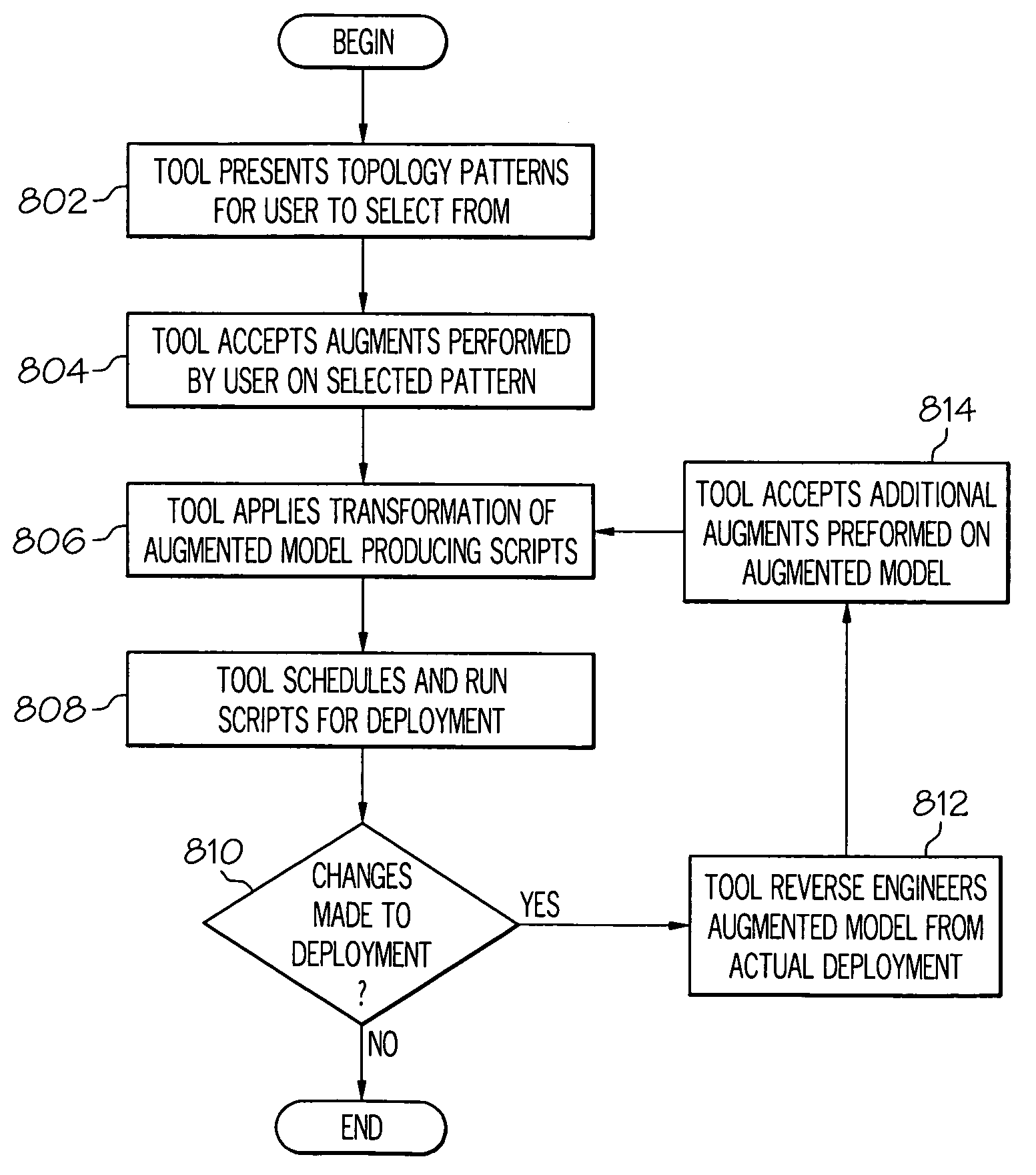
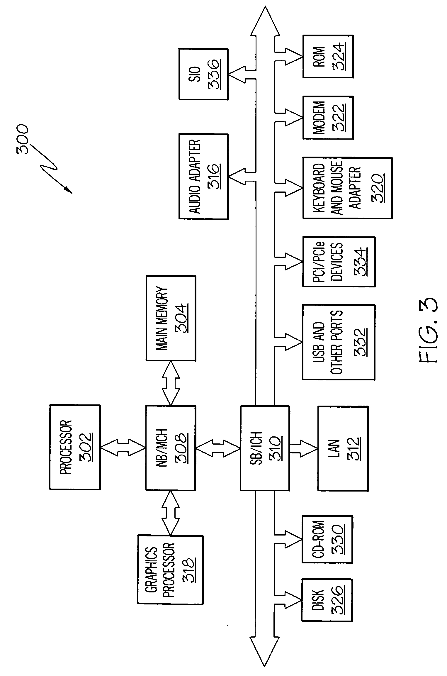
[0021]Aspects of the present invention provide a mechanism for modeling software deployments in an abstract method. The data processing device may be a stand-alone computing device or may be a distributed data processing system in which multiple computing devices are utilized to perform various aspects of the present invention. Therefore, the following FIGS. 1-3 are provided as exemplary diagrams of data processing environments in which the present invention may be implemented. It should be appreciated that FIGS. 1-3 are only exemplary and are not intended to assert or imply any limitation with regard to the environments in which the present invention may be implemented. Many modifications to the depicted environments may be made without departing from the spirit and scope of the present invention.

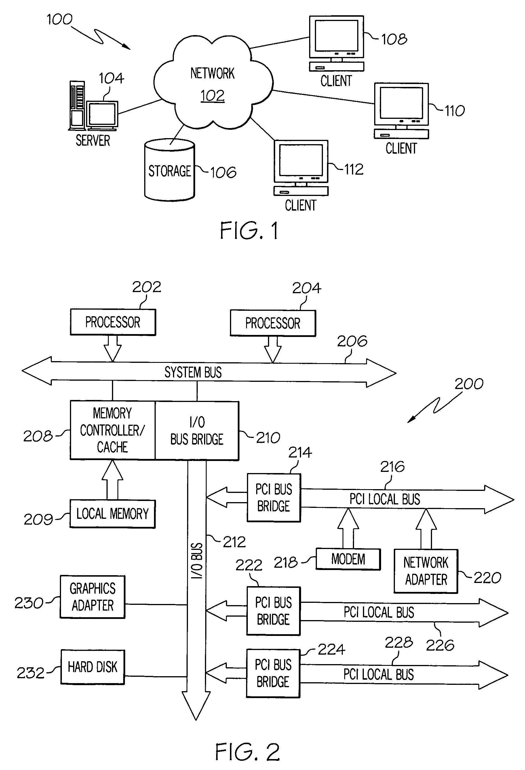
[0022]With reference now to the figures, FIG. 1 depicts a pictorial representation of a network of data processing systems in which the present invention may be implemented. Network data p...


PUM


Abstract

A method, system and computer program product is provided for deploying software in a data processing system. A topology pattern is selected in which the selected topology pattern describes an arrangement of software and hardware devices. Augments to the selected topology pattern are received to form an augmented topology pattern after a selection of a selected topology pattern from a plurality of topology patterns. The augmented topology pattern is transformed into a set of deployable scripts, wherein the set of deployable scripts is used for the software deployment.

Description

BACKGROUND OF THE INVENTION[0001]1. Field of the Invention[0002]The present invention relates generally to application deployment. Still more particularly, the present invention provides a method to use template diagrams, models or patterns to describe the topology consisting of physical software systems.[0003]2. Description of the Related Art[0004]The packaging of Java™ 2 Platform Enterprise Edition (J2EE™) applications are defined by the J2EE™ 1.2 specification. The intent of the specification is that Enterprise ARchive (EAR) files, the fundamental constructs that contain applications, be completely self-contained. Applications are expected to use Application Program Interfaces (APIs) provided by the J2EE™ server vendor, or those within the Enterprise ARchive, and nothing else. This way, applications can be independent of each other. This, in fact, is stated quite clearly in section 8.1.2 of the specification:[0005]A J2EE™ application consists of one or more J2EE™ modules and one ...

Claims


Application Information

Patent Timeline
Patent Type & Authority Patents(United States)
IPC IPC(8): G06F9/45
CPCG06F8/61
Inventor BROWN, KYLE GENELARSEN, GRANT J.MAJUMDAR, ARUNAVAMCELROY, THOMAS FRANCISVASUDEVA, GURUPRASAD CHITRAPUR
Owner IBM CORP
Why Eureka
Try Eureka