Disaster alert device and system

Inactive Publication Date: 2009-04-07
TREX ENTERPRISES CORP
View PDF17 Cites 191 Cited by
  • Summary
  • Abstract
  • Description
  • Claims
  • Application Information

AI Technical Summary

Benefits of technology

[0019]Alert warning devices may be distributed by mail and programmed by a computer before mailing that incorporates the appropriate latitude and longitude into the devices based on street addresses simultaneously with providing the address for mailing the device. The use position for the disaster alert device preferably is also printed on the device itself. Having control of the warning and who receives it permits emergency personnel at central offices to limit the warning to only those people within an at-risk region which can be as small as desired. The disaster alert devices can be very simple devices and mass production should cost less than $10. False alarms should be very rare. It is reasonable to expect that the devices will be utilized at least as universally as smoke detectors, both in residences and in work places. (In fact, in preferred embodiments, the disaster alert devices may be incorporated in a smoke detector or a smoke detector is incorporated in the device.) The devices may be required by public authorities or provided free of charge to persons living in some regions, such as flood plains, coastal regions subject to tsunami threats, regions near chemical plants, and regions near nuclear plants. They could also be required in new homes. Basically, there is no good reason not to have a disaster alert device according to the present invention located where you work and where you live.

Problems solved by technology

Knowledge of one of the keys, and the ability to use it to decrypt data does not give one the ability to derive the key used to perform the data encryption function (given sufficiently large key lengths).

Method used


Image

  • Disaster alert device and system
  • Disaster alert device and system
  • Disaster alert device and system

Examples


first preferred embodiment

Disaster Alert Device

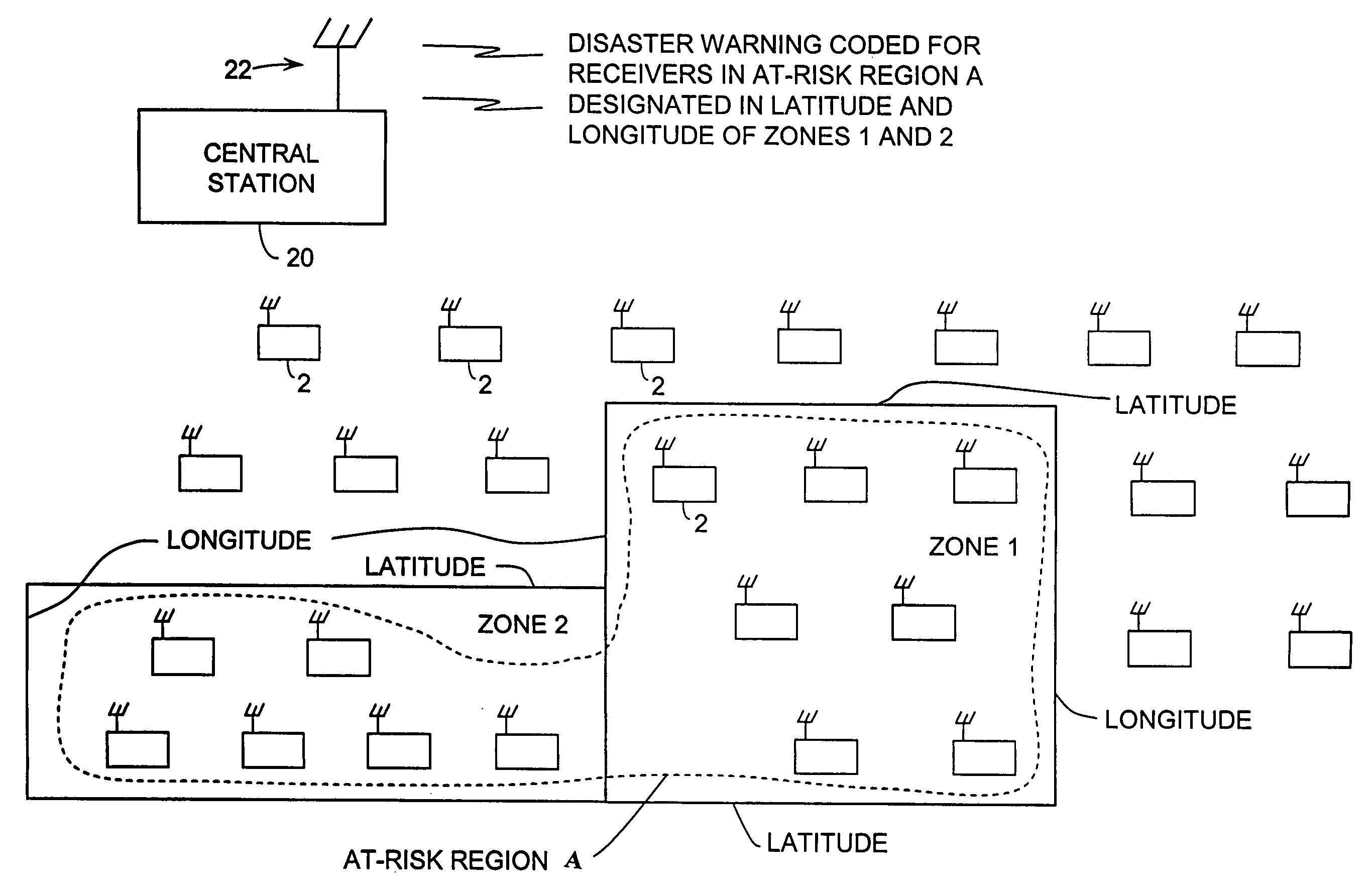
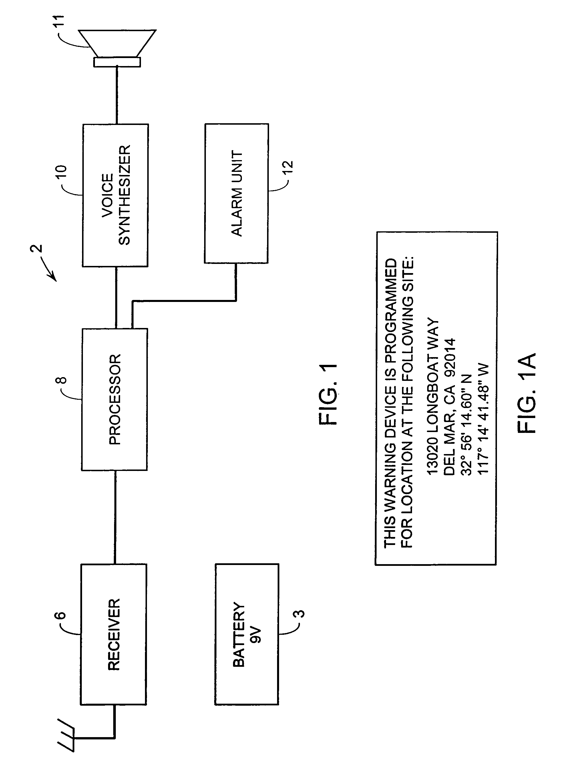
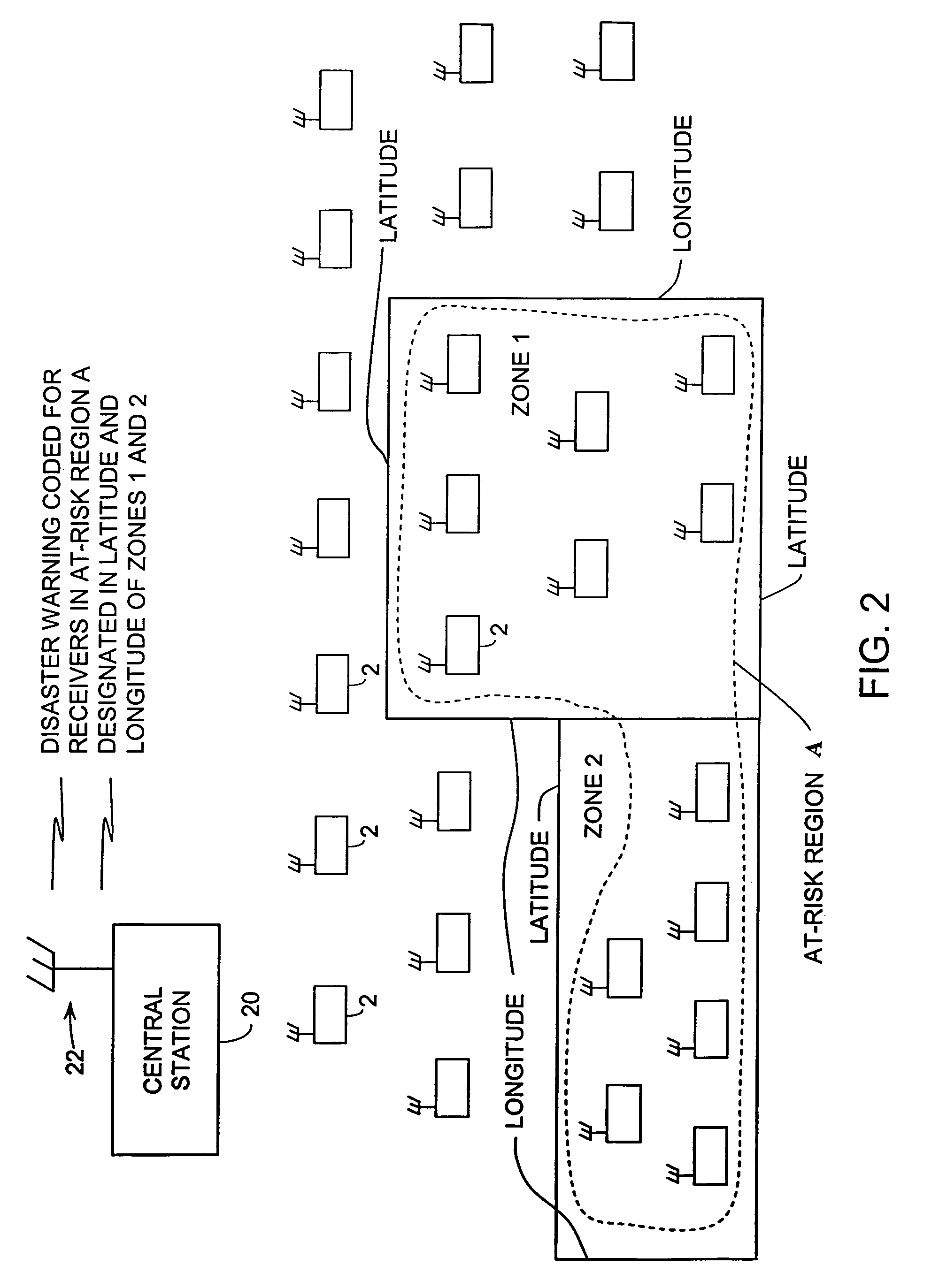
[0027]A first preferred embodiment of the present is described by reference to FIGS. 1, 1A, 2 and 4-7. FIG. 1 and 1A shows at 2 components of a preferred disaster alert device according to the present invention. The device is battery powered with a 9-volt battery 3 and also includes additional components for receiving and responding to disaster alert radio warnings. These additional components include radio receiver 6, processor 8, voice synthesizer 10, speaker 11, and alarm unit 12. As indicated in FIG. 1A each disaster alert device preferably is programmed by the supplier of the device with information identifying its “use location”. This programming can be done at a retail outlet at the time of sale, or it can be done in connection with mailing the device or in connection with the installation of the device if it is installed by the seller. Like a smoke detector, no programming by the consumer is required. This use location information includes the latitude a...


PUM


Abstract

A disaster alert system and disaster alert devices for use in the system. Each disaster alert device includes a radio receiver, and a processor programmed to monitor radio transmissions from one or more central stations for disaster alerts directed to the location of the disaster alert device. Each alert device also includes an audio unit to alert personnel located at the site of the device to the precise nature of the disaster. The disaster alert devices are pre-programmed with information identifying the precise use location of the warning device. This use location information includes latitude and longitude of the use location and may also include other location information such as street address and zip code. Warnings are broadcast from central stations identifying with latitude and longitude information specific at-risk regions to which the warnings are directed which could be, for example, nationwide, statewide, countywide, or to much smaller regions, such as several houses on a single street or even a single residence. Each disaster alert device is preferably programmed to ignore all warnings directed to at-risk regions that do not include the latitude and longitude of the use location of the device.

Description

[0001]This Application claims the benefit of Provisional Applications Ser. Nos. 60 / 795,922 filed Apr. 29, 2006 and 60 / 812,421 filed Jun. 10, 2006. This invention relates to disaster alert systems and in particular to such systems for providing alerts for actual or imminent disasters such as fires, tornados, tsunamis, floods, and terrorist attacks.BACKGROUND OF THE INVENTION[0002]Disaster alert devices are well known. A disaster alert device should be capable of waking-up and otherwise alerting people to pending danger and informing the people of the nature of the danger. Since disasters are normally very few and far between, people will be reluctant to purchase or use a warning device unless it is inexpensive, requires little or no attention, and produces very few false alarms. Since a disaster may interrupt outside power sources, the device should also not rely solely on outside power.Fire and Smoke Detectors[0003]Probably the most successful disaster alert device is the simple fir...

Claims


Application Information

Patent Timeline
Patent Type & Authority Patents(United States)
IPC IPC(8): G08B29/00
CPCG08B27/008
Inventor EISOLD, DOUGLAS C.PERKINS, BRENTJOHNSON, PAULFAIRCHILD, PAULTANG, KENETH Y.
Owner TREX ENTERPRISES CORP
Why Eureka
Try Eureka