Multi-user video conferencing with perspective correct eye-to-eye contact

a multi-user, eye-to-eye contact technology, applied in the field of videoconferencing systems, can solve the problems of inconvenient solution, inconvenient solution, and inability to accurately reflect the image of the remote participan

Active Publication Date: 2009-04-07
DREAMWORKS ANIMATION LLC
View PDF15 Cites 80 Cited by
  • Summary
  • Abstract
  • Description
  • Claims
  • Application Information

AI Technical Summary

Benefits of technology

[0008]The present invention provides various embodiments of a videoconferencing system and a method between sites providing correct perspective, multi-user eye-to-eye contact. The present invention provides the correct visual perspective for each local participant of each remote participant at the remote site thereby providing the visual sensation of being in the physical presence of the participants at the remote site and providing the appropriate eye-to-eye contact between each pair of participants.

Problems solved by technology

For viewers who are located to either side of the display system, the images of the remote participants do not have the correct perspective, since these viewers would normally see the remote participants from the side if in fact they were seated across from each other in the same conference room.
Similarly, as to the remote participants who are located off to the side of the camera axis, their images do not have the correct perspective either.
However, this solution is also not entirely correct since the “head on” display of each remote participant also does not provide the correct perspective based on each particular perspective of the remote participants.
There are a number of problems with Nakazawa's system.
First, as is clearly seen in FIG. 1, the position of each camera does not properly capture the perspective of the local participant as if he was located at the virtual location corresponding to the camera position and establishing eye contact with a remote participant.
A second problem with Nakazawa's system is that the design does not readily scale beyond the two-by-two configuration described.
Nakazawa states that in this design there are as many cameras and projectors as there are participants, but then admits that this approach is not realistic for implementation, and suggests that one camera and one projector be shared by multiple persons.
However, by definition, a single camera cannot correctly capture the proper perspective for eye-to-eye contact with between one participant (represented by the camera) and multiple remote participants.

Method used


Image

  • Multi-user video conferencing with perspective correct eye-to-eye contact
  • Multi-user video conferencing with perspective correct eye-to-eye contact
  • Multi-user video conferencing with perspective correct eye-to-eye contact

Examples


Embodiment Construction

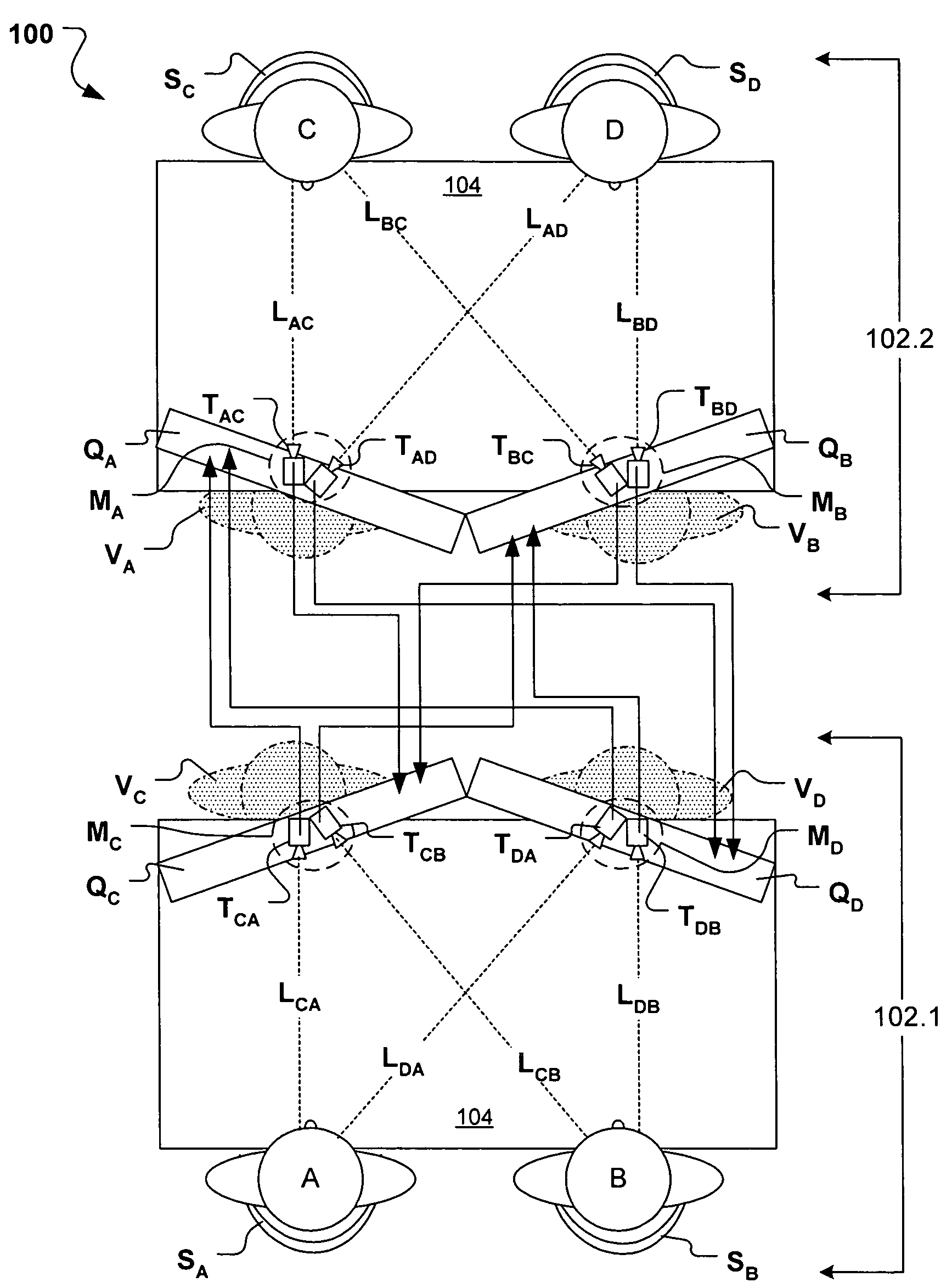
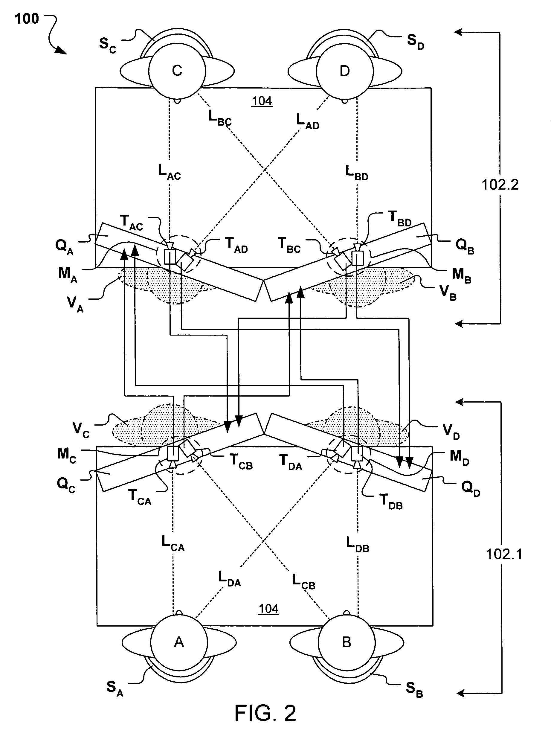
[0029]FIG. 2 illustrates a system 100 for visual communication between two sites 102.1, and providing perspective correct eye-to-eye contact between all of the participants at the sites 102.2. The nomenclature of FIG. 2 is as follows:

[0030]Participants are indicated as A, B, C, and D, and are located at respective actual viewing positions Si, where i indicates the participant.

[0031]Virtual viewing positions are designated Vi, where i corresponds to the participant (and hence actual viewing position) at the remote site. A virtual viewing position V thus has the perspective that a participant would have if sitting there. The virtual viewing positions V are illustrated as the grayed out body outlines of the participants.

[0032]A line of sight Lij identifies the orientation (or view) from a virtual viewing position Vi to actual viewing position Sj where participant j would be located.

[0033]Image capture devices (e.g., cameras) are designated Tij, where i designates the remote participant...


PUM


Abstract

A video conferencing system provides perspective correct eye-to-eye interaction for multiple participants at sites remote from each other. The system provides at each site a configuration of participant viewing positions, a multidirectional image capture system for capturing images of each position at one site from the perspective of each viewing position at the other site, and a multidirectional display system for displaying images of each viewing position at the other site from the perspective of each viewing position at the one site.

Description

FIELD OF INVENTION[0001]The invention relates generally to a videoconferencing system between remote sites that provides proper perspective and eye contact between the participants.BACKGROUND OF THE INVENTION[0002]A basic teleconferencing system typically includes at each respective site a camera for capturing a view of the participants at that site and a display for displaying a view of the participants at the other site. In traditional high end teleconferencing designs, multiple cameras are used for capturing images of participants at a site, with no (or minimal) overlap and multiple displays at another site display these different captured images. In either of these types of configurations, each display shows the image of the remote participants with a perspective that is determined by the position of the camera, which is coupled to that display. In some cases, a single camera is centrally positioned over the display device(s), and captures a wide field of view of the site. In th...

Claims


Application Information

Patent Timeline
Patent Type & Authority Patents(United States)
IPC IPC(8): H04N7/14G02B5/32
CPCG02B27/2214H04N7/144H04N7/15G02B30/27
Inventor FRANCISCO, EMMANUEL C.LEONARD, EDWIN R.
Owner DREAMWORKS ANIMATION LLC
Why Eureka
Try Eureka