RC-triggered power clamp suppressing negative mode electrostatic discharge stress
a technology of negative discharge and power clamp, which is applied in the direction of emergency protective arrangement details, emergency protective arrangement for limiting excess voltage/current, electrical apparatus, etc., can solve the problems of diodes occupying valuable silicon area, not optimized for esd stress, and weak rc-triggered power clamping
- Summary
- Abstract
- Description
- Claims
- Application Information
AI Technical Summary
Benefits of technology
Problems solved by technology
Method used
Image
Examples
Embodiment Construction
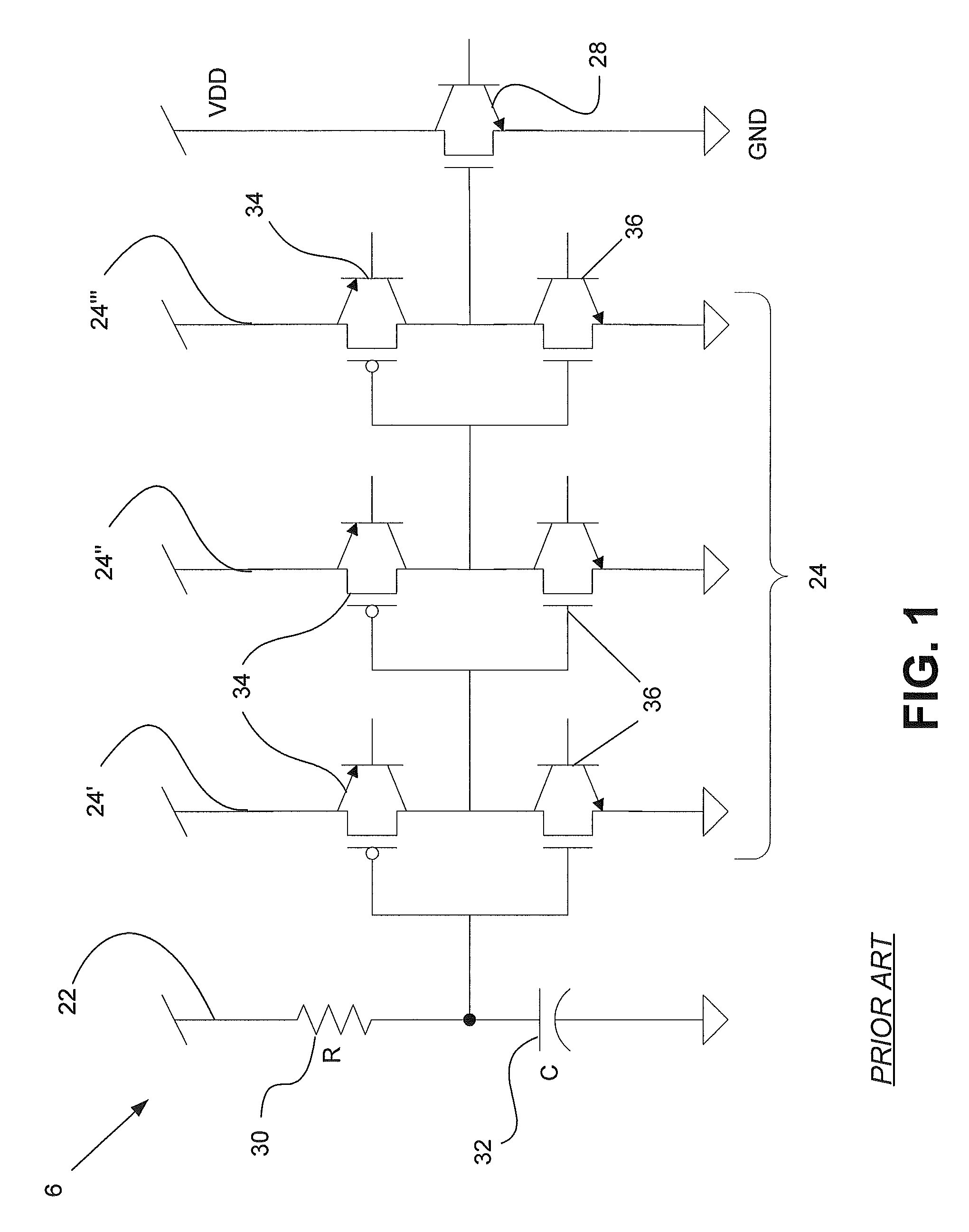
[0015]Referring now to the figures, FIG. 1 illustrates a conventional power clamp circuit 6. Power clamp circuit 6 includes an RC-delay or triggering element 22 having a resistor 30 connected in series with a capacitor 32. RC-delay element 22 is connected in series with a plurality of serialized inverters 24 connected in series with a power clamp element 28. Power for circuit 6 is typically supplied by a voltage supply referred to as VDD with ground represented by GND. During all ESD events, inverters 24 trigger on power clamp element 28 to conduct current. Power clamp circuit 6 is generally designed for positive mode ESD events. However, power clamp circuit 6 conducts poorly during negative mode ESD events.
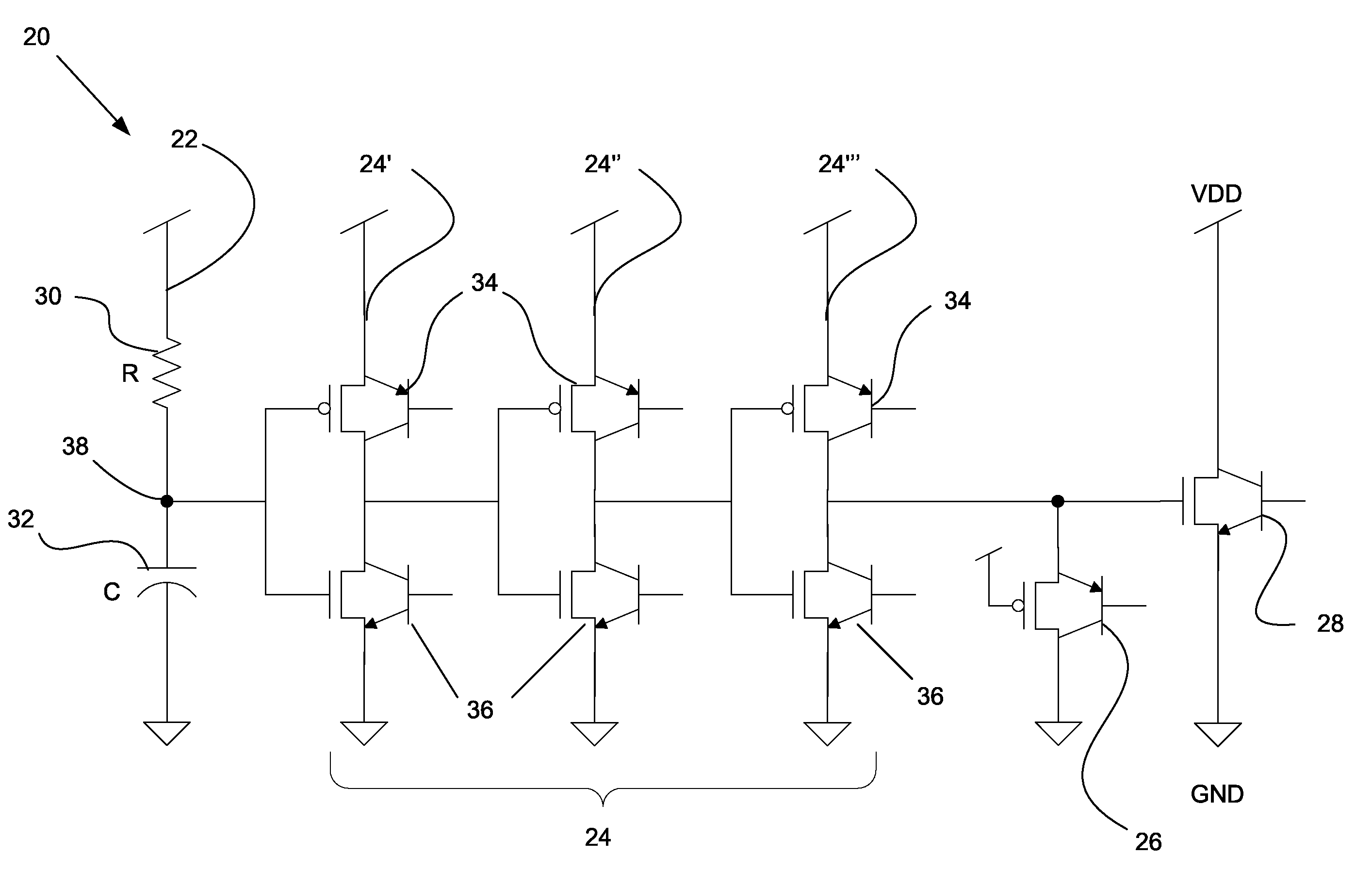
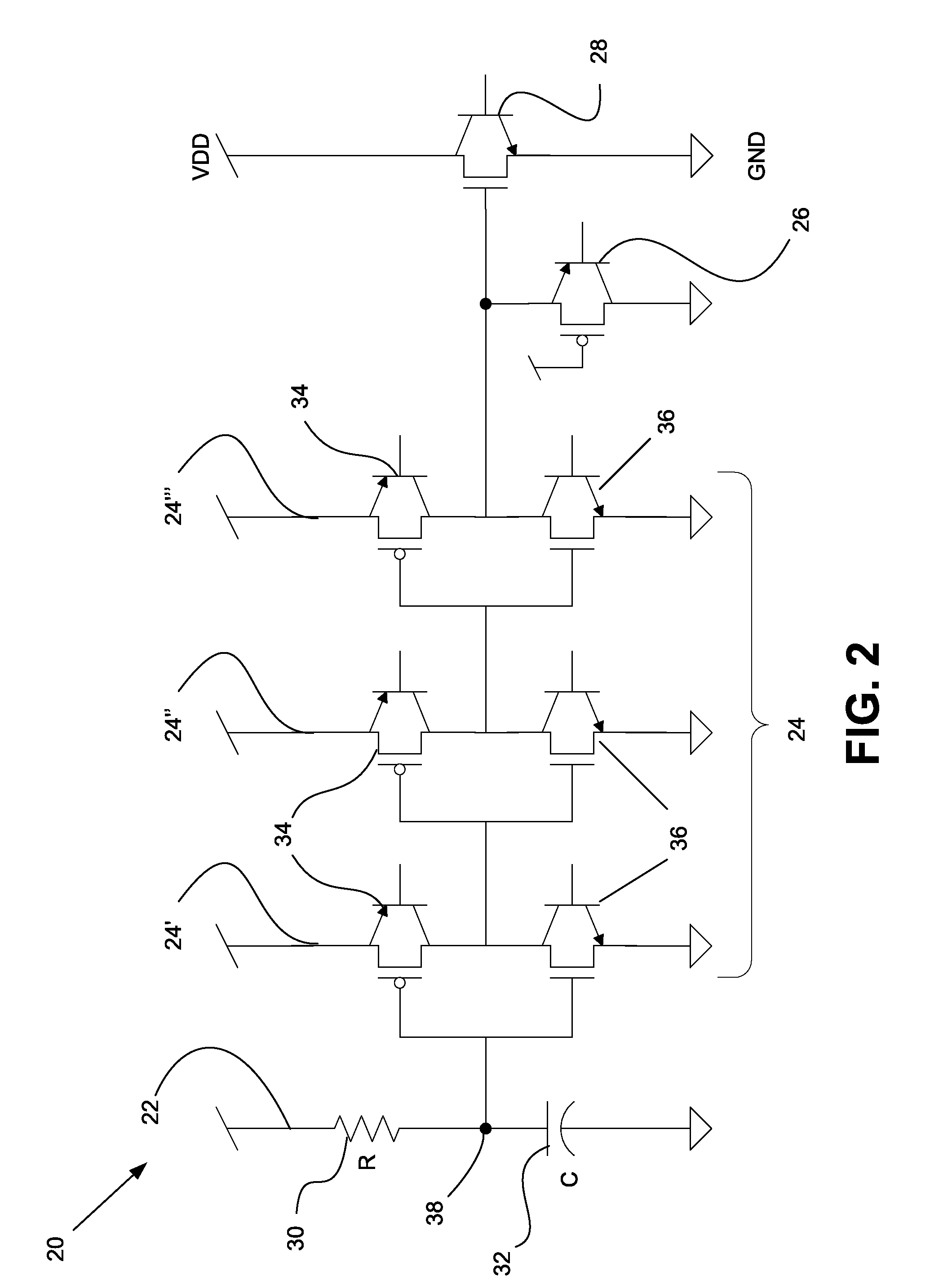
[0016]FIG. 2 illustrates one embodiment of the disclosure showing a floating-body NFET-based power clamp circuit 20 for detecting and controlling both negative and positive modes of electrostatic discharge (ESD) stress. Circuit 20 protects against all types of ESD stress events i...
PUM
 Abstract
Description
Claims
Application Information
 - R&D
- Intellectual Property
- Life Sciences
- Materials
- Tech Scout
- Unparalleled Data Quality
- Higher Quality Content
- 60% Fewer Hallucinations
Browse by: Latest US Patents, China's latest patents, Technical Efficacy Thesaurus, Application Domain, Technology Topic, Popular Technical Reports.
© 2025 PatSnap. All rights reserved.Legal|Privacy policy|Modern Slavery Act Transparency Statement|Sitemap|About US| Contact US: help@patsnap.com


