
Method and arrangement for optimizing efficiency of a power amplifier

a power amplifier and efficiency technology, applied in the field of transmitters, can solve the problems of complex implementation, slow amplifier calibration process, high power loss in controllable power supply, etc., and achieve the effect of fast and easy

Active Publication Date: 2009-04-14
NOKIA TECH OY
View PDF10 Cites 30 Cited by
  • Summary
  • Abstract
  • Description
  • Claims
  • Application Information

AI Technical Summary

Benefits of technology

[0005]It is an objective of the present invention to provide an envelope tracking power amplifier the efficiency of which can be optimized so that the limitations and drawbacks associated with prior art are eliminated or reduced. It is also an object of the present invention to provide a mobile communication device having an envelope tracking power amplifier the efficiency of which can be optimized so that the limitations and drawbacks associated with prior art are eliminated or reduced. It is also an object of the present invention to provide a method for optimizing efficiency of an envelope tracking power amplifier so that the limitations and drawbacks associated with prior art are eliminated or reduced. It is also an object of the present invention to provide a transmitter that can be used e.g. in a mobile communication device so that the limitations and drawbacks associated with prior art are eliminated or reduced.

Problems solved by technology

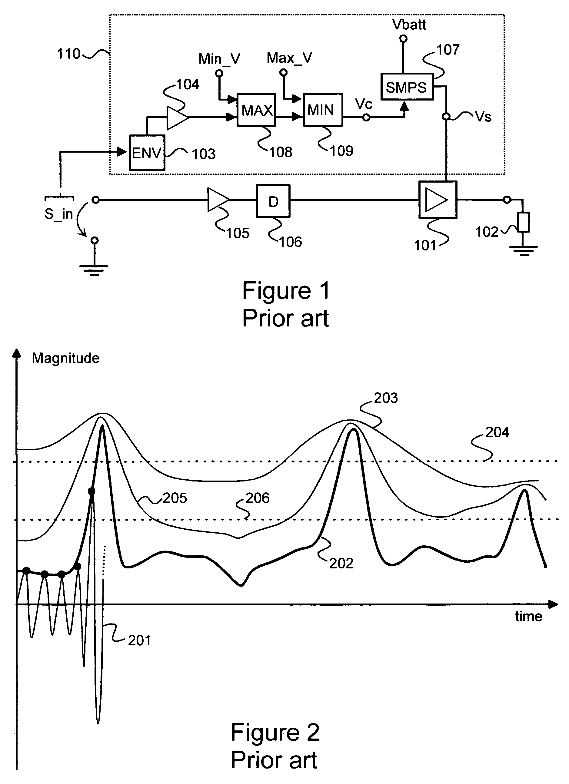
High accuracy required in the delay adjustment means a complex implementation and a slow calibration process of the amplifier.
Furthermore a high value of the control bandwidth means high power losses in the controllable power supply 107 in FIG. 1.
A situation is especially disadvantageous when the envelope 202 has a low time average and high sharp peaks.

Method used


Image

  • Method and arrangement for optimizing efficiency of a power amplifier
  • Method and arrangement for optimizing efficiency of a power amplifier
  • Method and arrangement for optimizing efficiency of a power amplifier

Examples


Embodiment Construction

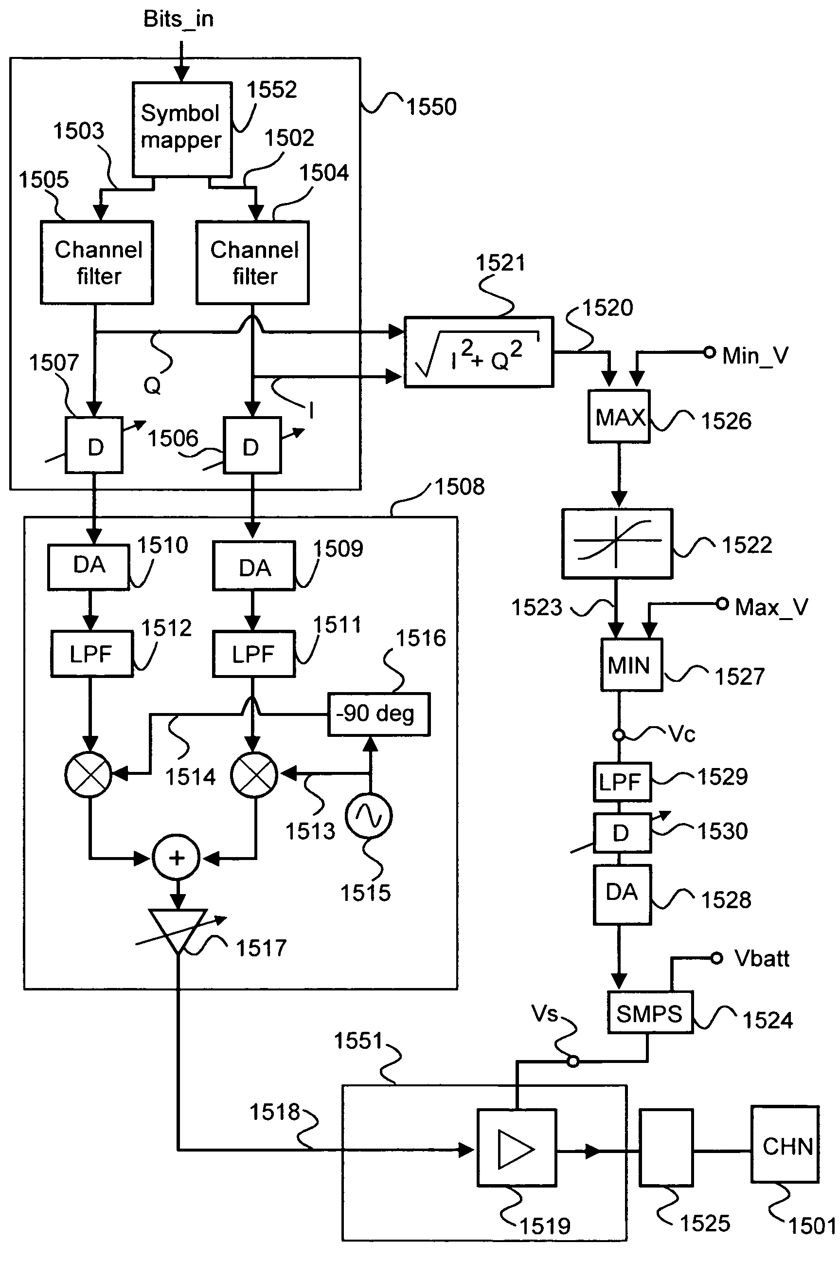
[0045]FIGS. 1-2 have been explained above in the description of the prior art.

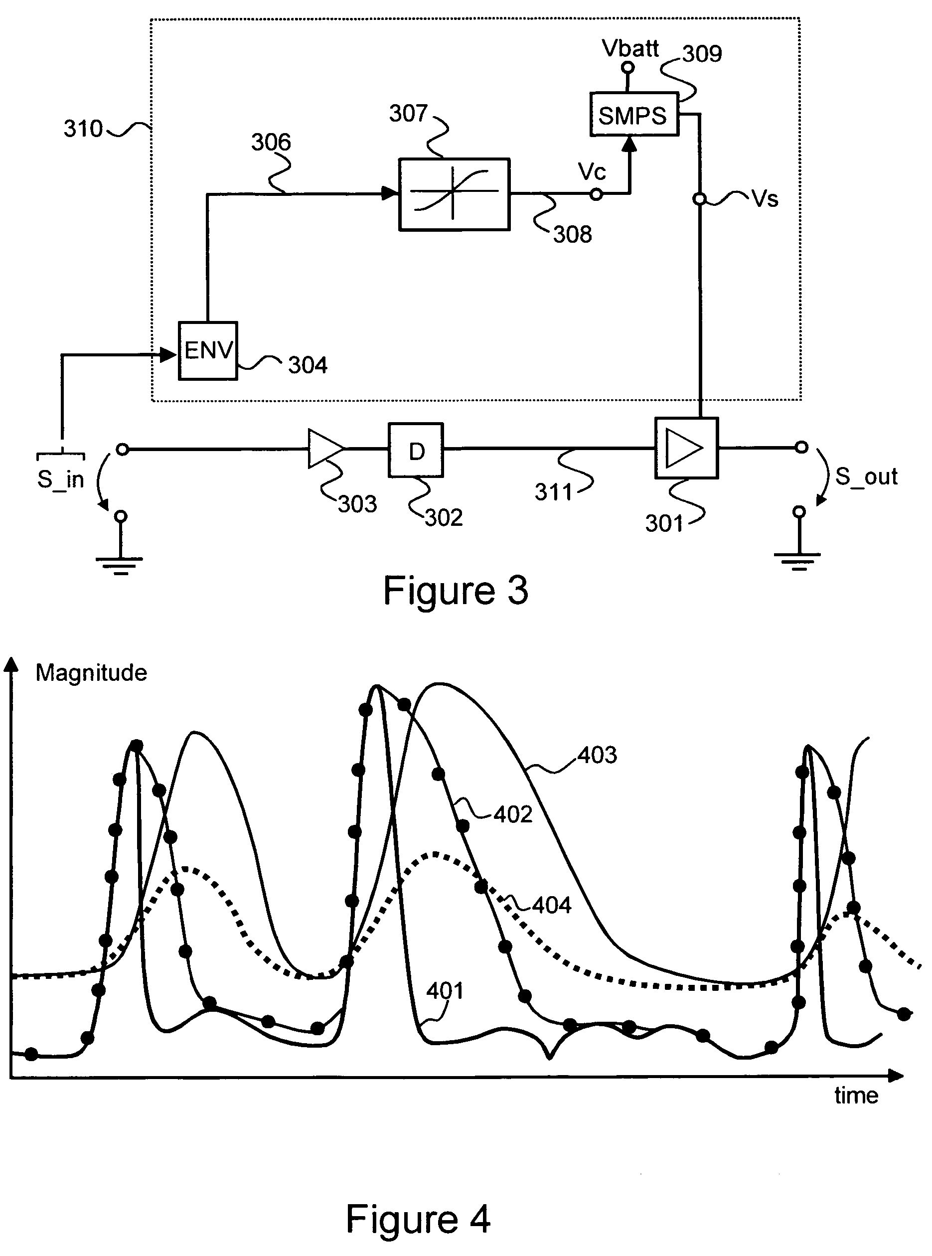
[0046]FIG. 3 shows a high-level block diagram of an envelope tracking power amplifier according to an embodiment of the invention. An envelope signal 306 representing an envelope of an input signal S_in is detected with an envelope detector 304. From the viewpoint of the principle of operation it is immaterial whether the envelope is detected from the input signal S_in or from some other signal from which information associated with the envelope can be extracted. In many applications the input signal S_in is produced with a base band stage and an up-modulator; the base band stage and the up-modulator are not shown in FIG. 3. In these applications it is possible to detect the envelope from the base band signal.

[0047]The envelope signal 306 is filtered with a non-linear filter 307 that produces a filtered envelope signal 308. The non-linear filter 307 is disposed to filter the envelope signal 306 so that a r...


PUM


Abstract

The invention relates to optimizing efficiency of a power amplifier of a transmitter. In a solution according to the invention a detected envelope (306) of an input signal of the power amplifier is filtered with a non-linear filter (307) that substantially preserves a rise time of a peak in a waveform of the envelope but lengthens a temporal duration of the peak. A filtered envelope is used as an input quantity (308) for a control system that controls a supply voltage of the power amplifier. For the control system it is easier to react to peaks of the filtered envelope than to the peaks of the envelope because the temporal duration of the peaks of the filtered envelope is longer than that of the peaks of the envelope.

Description

FIELD OF THE INVENTION[0001]The invention relates to a transmitter for communicating devices. The invention especially relates to optimizing efficiency of a power amplifier of a transmitter.BACKGROUND OF THE INVENTION[0002]In order to optimize efficiency of a power amplifier one needs to keep a supply voltage of the power amplifier as low as possible; in this document the efficiency means: output signal power / (input signal power+energizing power of the power amplifier). On the other hand the supply voltage has to be high enough that no clipping occurs in an output signal of the power amplifier. In an envelope tracking power amplifier an envelope of an input signal of the amplifier is detected and the supply voltage is a function of the detected value of the envelope. The power amplifier operates close to a compression point on all envelope values and thus provides a good efficiency. Keeping the supply voltage at an optimal value is a challenging task especially when the output signa...

Claims


Application Information

Patent Timeline
Patent Type & Authority Patents(United States)
IPC IPC(8): H04B1/04
CPCH03F1/0222H03F1/0227H03G3/004H03F2200/102
Inventor VEPSALAINEN, JUSSIMATERO, JORMA
Owner NOKIA TECH OY
Learn More