Method and arrangement for optimizing efficiency of a power amplifier

a power amplifier and efficiency optimization technology, applied in the field of transmitters, can solve the problems of significant computation capacity and complex practical realization, poor efficiency of the amplifier stage having the 1 v peak voltage, and inconvenient optimization of the amplifier stage efficiency, so as to achieve simple and cost-effective

Active Publication Date: 2007-05-24
NOKIA TECHNOLOGLES OY
View PDF9 Cites 33 Cited by
  • Summary
  • Abstract
  • Description
  • Claims
  • Application Information

AI Technical Summary

Benefits of technology

[0013] realization is simple and cost effective; no need for directional switches for efficiency optimization.

Problems solved by technology

For example, in an impedance matched situation the peak voltages can be 2 V for both of the signals S1 and S2 but in an impedance mismatch situation the corresponding peak voltages can be 1 V and 3 V. Due to the fact that the supply voltage Vs needs to be so high that the signal with the 3 V peak voltage is not clipped, the efficiency of the amplifier stage having the 1 V peak voltage is poor.
This principle is, however, not suitable for optimizing efficiencies of the amplifier stages due to the fact that the peak voltages vary with varying load impedance even if output power of the amplifier remains constant.
The above-referred methods require, however, significant computation capacity and practical realizations are complex.
Furthermore, these methods are not suitable for a balanced amplifier of the kind described above.

Method used


Image

  • Method and arrangement for optimizing efficiency of a power amplifier
  • Method and arrangement for optimizing efficiency of a power amplifier
  • Method and arrangement for optimizing efficiency of a power amplifier

Examples


Embodiment Construction

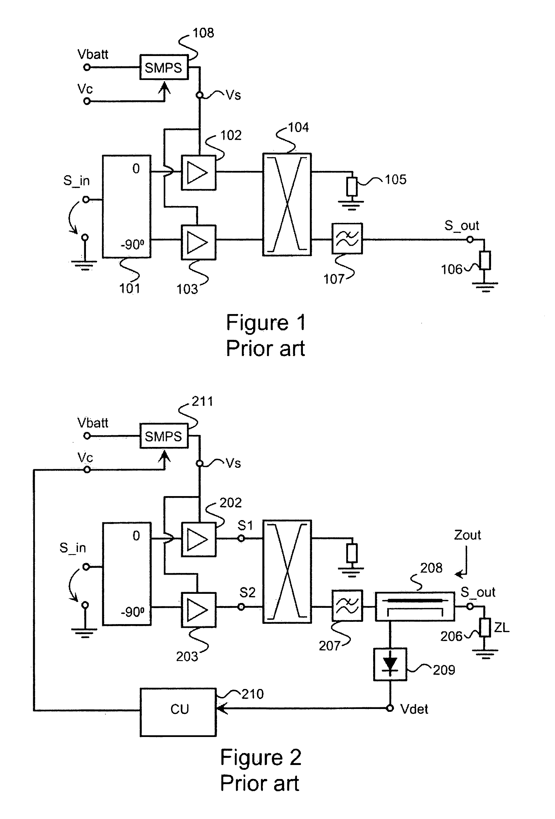
[0055]FIGS. 1-2 have been explained above in the description of the prior art.

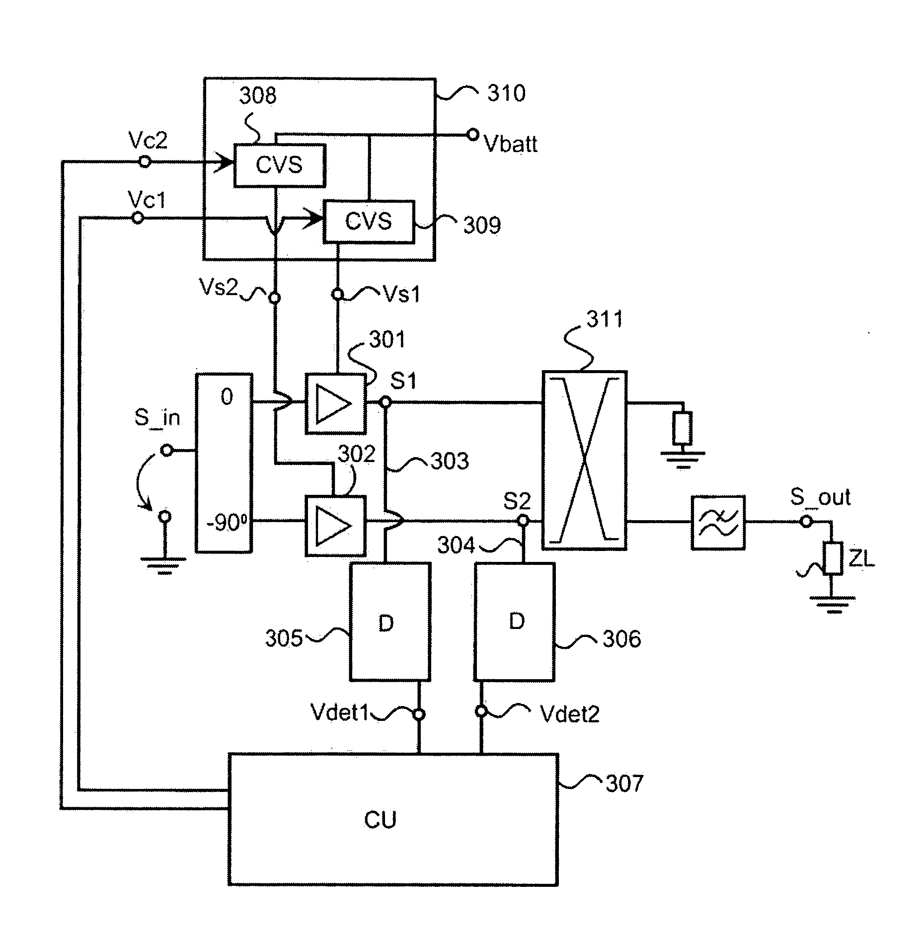
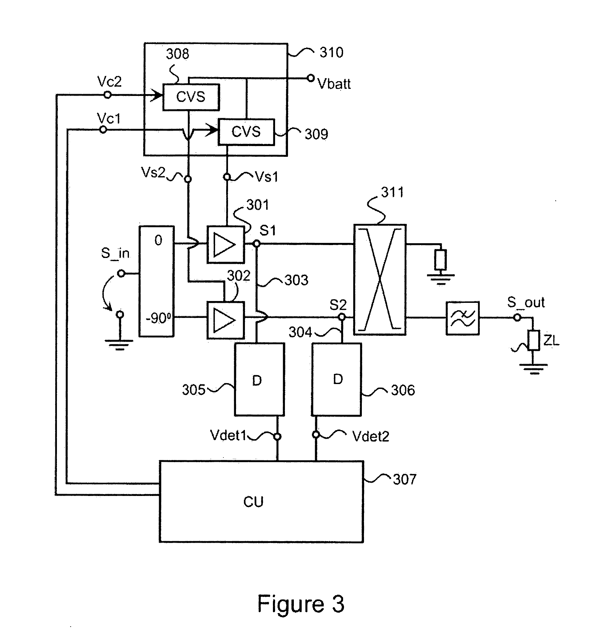
[0056]FIG. 3 shows a balanced power amplifier according to an embodiment of the invention. The balanced power amplifier comprises an in-phase amplifier stage 301 and a quadrature amplifier stage 302. Supply voltages Vs1 and Vs2 for the in-phase and quadrature amplifier stages 301 and 302 are produced with a controllable supply unit 310. The controllable supply unit 310 comprises two controllable voltage sources 308 and 309 that can be for example switched mode power supplies (SMPS) according to prior art or linear regulators according to prior art. A type of the controllable voltage sources is immaterial from the viewpoint of the invention. In the remainder of this document an output signal S1 of the in-phase amplifier stage 301 is called an in-phase signal and an output signal S2 of the quadrature amplifier stage 302 is called a quadrature signal. The in-phase signal S1 is conducted via a signal path 303...


PUM


Abstract

The invention relates to optimizing the efficiency of a power amplifier of a transmitter. The objectives of the invention are achieved with a solution in which a voltage level of an output signal of an amplifier stage (301, 302) is detected (305, 306) at a signal output of each amplifier stage and the detected information is used for controlling a supply voltage of each amplifier stage in a way so that the unnecessarily high levels of the supply voltages can be avoided thus improving efficiency of the power amplifier.

Description

FIELD OF THE INVENTION [0001] The invention relates to a transmitter for communicating devices. The invention especially relates to optimizing efficiency of a power amplifier of a transmitter. BACKGROUND OF THE INVENTION [0002] In order to optimize efficiency of a power amplifier one needs to keep a supply voltage of the power amplifier as low as possible; in this document the efficiency means 1−power losses / output power. On the other hand the supply voltage has to be high enough that no clipping occurs in an output signal of the power amplifier. Keeping the supply voltage at an optimal value is a challenging task especially when an impedance of a circuitry loading the power amplifier varies. For example, in a mobile communication device an impedance of an antenna loading a power amplifier varies considerably with frequency and with external circumstances. An example of external circumstances that has an effect on the impedance of the antenna is the position of user's fingers in the...

Claims


Application Information

Patent Timeline
Patent Type & Authority Applications(United States)
IPC IPC(8): H03F3/68
CPCH03F1/0205H03F1/0238H03F1/32H03F3/19H03F3/24H03F2200/192H03F2200/198H03F2200/204H03F2200/336H03F2200/351H03F2200/451H03F2200/516H03F2200/99
Inventor VAISANEN, RISTO
Owner NOKIA TECHNOLOGLES OY
Why Eureka
Try Eureka