
Method for operating a power-assist braking system

a technology of brake assistant and brake assistant, which is applied in the direction of brake system, automatic initiation, transportation and packaging, etc., can solve the problems of unnoticeable reducing of brake assistant support for the driver, unsatisfactory and unsafe operation state, etc., and achieves simple and cost-effective realization and the rate at which the excess elevation is reduced

Inactive Publication Date: 2007-03-13
CONTINENTAL TEVES AG & CO OHG
View PDF14 Cites 7 Cited by
  • Summary
  • Abstract
  • Description
  • Claims
  • Application Information

AI Technical Summary

Benefits of technology

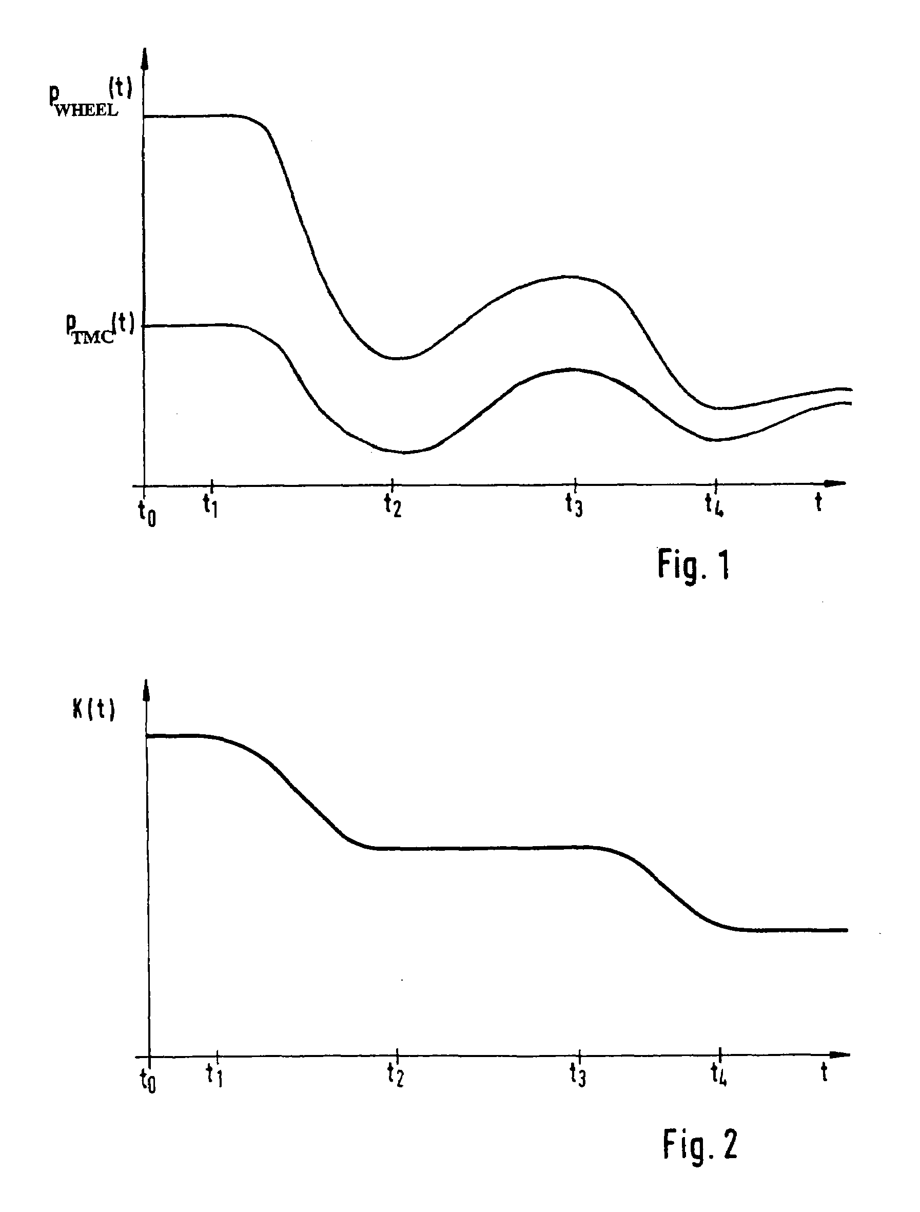
[0008]A special advantage of the invention consists in that a once-initiated transition to conventional braking behavior is not being maintained for a longer time period. Otherwise, this would, e.g. while going downhill, result in an undesired and unsafe state of operation.
[0009]Preferably, the excess elevation is dependent on the driving situation and / or the input of a vehicle driver my means of the brake pedal. Thus, the brake force support can be tuned to the driving conditions in the best possible way. Also, in this case, a harmonic correlation can be ensured between the driver's directive and the pressure raise.
[0010]Preferably, the rate at which the excess elevation is reduced increases with the time duration and / or the intensity of a reduction of pedal force induced by the vehicle driver. A reduction of pedal force indicates a driver's intention that a brake operation is not necessary or not necessary as forceful any more. The input control by the driver can be used in an advantageous way to design the transition of the brake assistant function to the conventional brake operation.
[0011]A particularly simple and cost-effective realization of the invention results from using a counting device to recognize whether and / or by what amount the driver reduces the pedal force.
[0012]In order to implement the invention, it is preferred if the momentary value of the wheel brake pressure results substantially from a multiplication of a current value of a time-dependent excess elevation function and the current value of the tandem master cylinder pressure.
[0013]And the excess elevation function, as a function of time, is monotonously descending.

Problems solved by technology

Otherwise, this would, e.g. while going downhill, result in an undesired and unsafe state of operation.
In this way, the brake assistant support can be diminished unnoticeably for the driver.

Method used


Image

  • Method for operating a power-assist braking system
  • Method for operating a power-assist braking system
  • Method for operating a power-assist braking system

Examples


Embodiment Construction

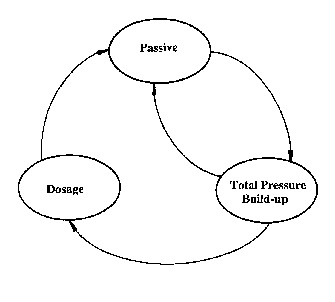
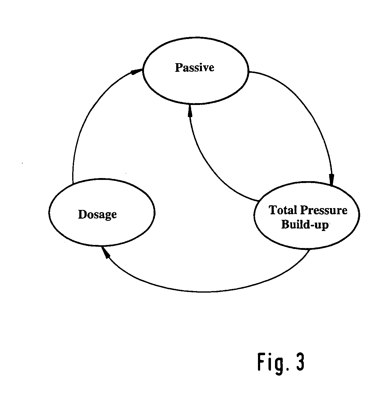
[0020]In FIG. 3, three kinds or modes of operation of the brake assistant system according to the invention are schematically depicted. From FIG. 3 can be obtained the function of the brake assistant system as an automaton of states. The first state or mode of operation “Passive” means that the brake assistant function is not active. As soon as an emergency braking situation is recognized, the system changes over into the second state or mode of operation “Total Pressure Build-up”. In this state, a total pressure build-up is generated by means of a return pump and suitable control of separating and switch-over valves. From the state “Total Pressure Build-up”, a change can be made as well into the state of passivity into the third mode of operation, the dosage mode if the pedal force is significant reduced which can be detected e.g. through the pressure sensor device arranged in the tandem master cylinder. Higher-ranking criteria for the activation of the state “Dosage” out of the st...


PUM


Abstract

In a method of operating a brake assistant system which includes a first mode of operation in which the brake assistant system is not operated, a second mode of operation in which, after recognition of an emergency brake situation, a pressure build-up of wheel brakes is generated, and a third mode of operation which is provided for the transition from the second into the first mode of operation, wherein in the third mode of operation the wheel brake pressure (pWHEEL) is excessively elevated compared to the tandem master cylinder pressure (pTMC) in a controlled way, a particularly safe and user-friendly termination of the brake assistant system results from diminishing the amount of the excess elevation over the course of time.

Description

TECHNICAL FIELD[0001]The present invention generally relates to vehicle brake systems and more particularly relates to a method of operating a brake assistant system.BACKGROUND OF THE INVENTION[0002]In order to realize a shortest possible stopping distance of automobiles in emergency brake situations, it is necessary to excessively raise the brake pressure with respect to a pedal force initiated by the driver. Since studies have yielded the result that, in emergency brake situations, normal drivers often cannot or only with a delay induce the required pre-pressure, so-called “brake assistant systems” were developed which raise the brake pressure automatically above the level pre-determined by the driver.[0003]In principle, there are three known systems. In a first one, the brake pressure is raised by means of an automatic control of the brake booster. In the second one, the active pressure raise occurs through suitable control of the ABS / ESP hydraulics by means of the electric retur...

Claims


Application Information

Patent Timeline
Patent Type & Authority Patents(United States)
IPC IPC(8): B60T8/66B60T7/12B60T8/32B60T13/66
CPCB60T7/12B60T13/662B60T8/3275Y10S303/02
Inventor HECKER, OLIVERRITZ, STEFFEN
Owner CONTINENTAL TEVES AG & CO OHG
Learn More