Rough in box for use in protecting a plumbing drain line during pouring of concrete

a technology for drain lines and boxes, applied in forms/shuttering/falseworks, artificial islands, foundation engineering, etc., can solve problems such as inconvenience of manually fashioning stud constructions, inconvenience of jobsite, and many shortcomings, and achieve the effect of improving and effectiv

Inactive Publication Date: 2009-05-19
DAIGGER DANIEL J +2
View PDF16 Cites 11 Cited by
  • Summary
  • Abstract
  • Description
  • Claims
  • Application Information

AI Technical Summary

Benefits of technology

[0009]The present invention discloses a form assembly for use with a rough-in floor drain line and in order to protect the drain line during the subsequent pouring of a volume of concrete upon a surrounding ground location. As previously described, the form assembly of the present invention provides an improvement over prior art assemblies, including in particular 2″×4″ stud assemblies, in that it provides an improved and effective device for isolating and safeguarding (such as maintaining accessibility to) the rough-in drain line during pouring of the concrete, which is typically involved with new construction basements or concrete slabs such as southern housing or commercial / industrial buildings.

Problems solved by technology

While providing a somewhat effective solution for isolating and protecting a roughed-in floor drain, such 2″×4″ stud constructions suffer from a number of shortcomings, including having to be forcibly disassembled from the encircling poured concrete.
The result of this is typically lost time on the jobsite and the inconvenience of manually fashioning such stud constructions.

Method used


Image

  • Rough in box for use in protecting a plumbing drain line during pouring of concrete
  • Rough in box for use in protecting a plumbing drain line during pouring of concrete
  • Rough in box for use in protecting a plumbing drain line during pouring of concrete

Examples


Embodiment Construction

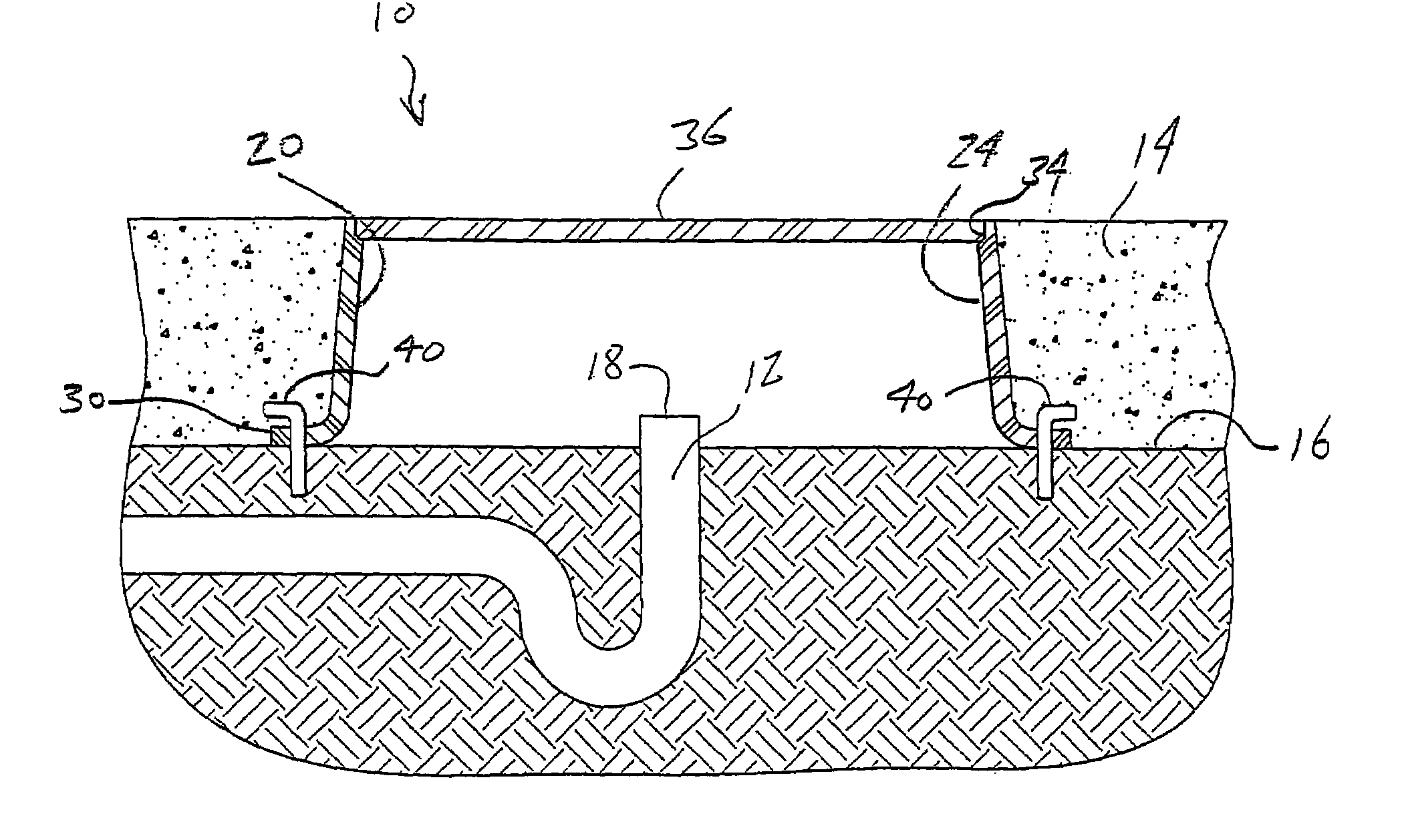
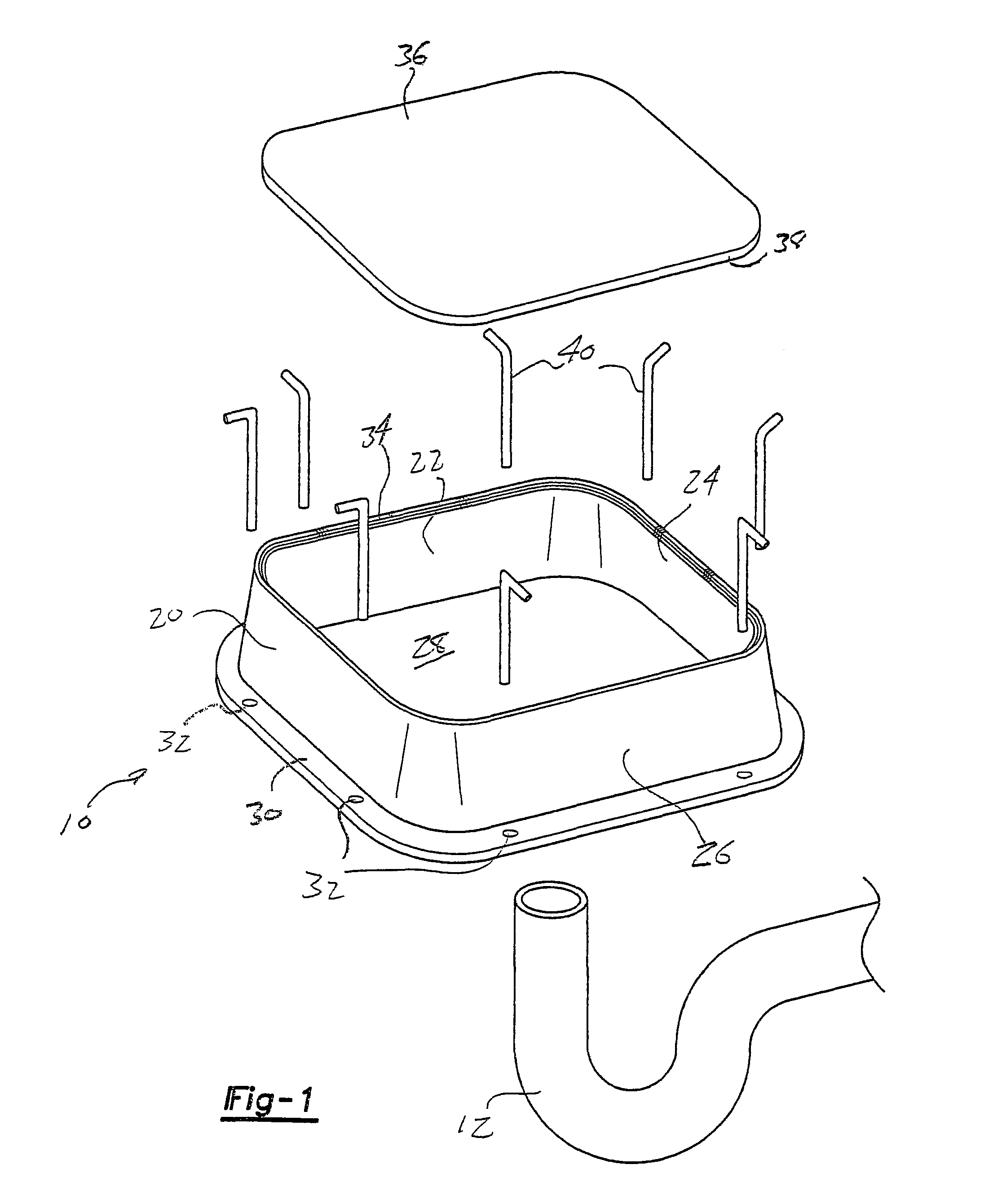
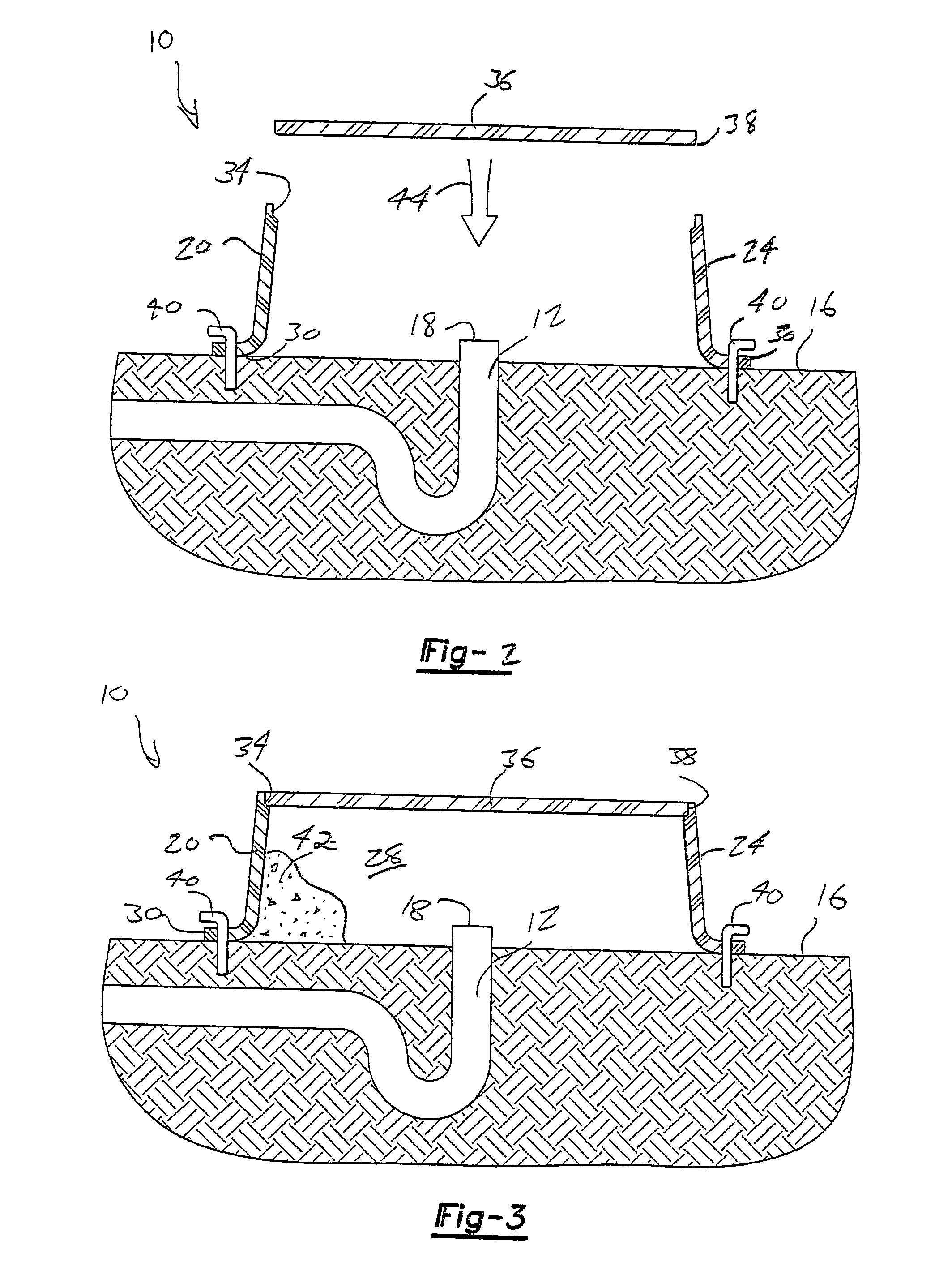
[0018]Referring now to FIG. 1, an exploded view is illustrated generally at 10 of a form assembly for use with a rough-in floor drain line 12. As previously described, and with succeeding reference to FIGS. 2-4, the form assembly 10 exists to protect the drain line 12 during the subsequent pouring of a volume of concrete 14 (FIG. 4), according to any depth, and upon a surrounding earthen ground location 16. As also previously described, the form assembly of the present invention provides an improvement over prior art assemblies, including in particular 2×4 stud assemblies, in that it provides an improved and effective device for isolating and safeguarding the rough-in drain line during pouring of the concrete, and which is typically involved with new construction basements.

[0019]Referring again to FIGS. 1-4, the roughed-in (basement or industrial) drain line 12 is further typically provided for bathtubs, whirlpool tubs, showers, mop sink rough-in lines, and the like, and extends in ...


PUM


Abstract

A form assembly for use with a rough-in floor drain line, extending from a ground location prior to the pouring of a concrete aggregate. A body is constructed of a plasticized material and exhibits a three-dimensional outline with a height, width and depth and an open interior. The body further includes a bottom-most extending and encircling lip and an upper rim edge. The body is positioned so that the open interior surrounds the exposed floor drain line and a volume of a sand aggregate is filled into the open interior over and around the exposed drain. A lid is secured over the rim edge and a plurality of elongated and ground-securing stakes are engaged through apertures associated with the bottom extending said lip, in order to secure the body upon the ground location and to isolate the floor drain line from a volume of encircling and poured concrete.

Description

BACKGROUND OF THE INVENTION[0001]1. Field of the Invention[0002]The present invention relates generally to forms used for covering plumbing drain lines. In particular, the present invention discloses a molded and plasticized form (such as may also be constructed of foam) which is secured over a rough-in area in which a plumbing drain line, prior to the pouring of a cement floor, and which isolates the upwardly angled drain line from the encircling cement and prevents the concrete from encroaching within the rough-in area.[0003]2. Description of the Prior Art[0004]The prior art is documented with examples of protection devices and schemes for use with protecting and providing access to floor drain lines and the like. One known example is the construction of boxes, composed of assembled 2″×4″ wooden studs, and constructed so as to be placed over a roughed-in floor drain area. The rough-in 2″×4″ construction is normally used in order to isolate and protect the rough-in drain at the tim...

Claims


Application Information

Patent Timeline
Patent Type & Authority Patents(United States)
IPC IPC(8): E02D19/00E03F5/04E04B5/48E04G15/06
CPCE03F5/0407E04B5/48E04G15/061
Inventor DAIGGER, DANIEL J.MOORE, RODNEY K.CLARK, MARLOW G.
Owner DAIGGER DANIEL J
Why Eureka
Try Eureka