Method for Transferring Data Packets

Inactive Publication Date: 2008-07-17
NOKIA SIEMENS NETWORKS GMBH & CO KG
View PDF15 Cites 1 Cited by
  • Summary
  • Abstract
  • Description
  • Claims
  • Application Information

AI Technical Summary

Benefits of technology

[0012]The object of the invention is therefore to give an improved and more eff

Problems solved by technology

With relatively high traffic density, greater delays in sending data bursts occur, since fewer free time slots are available for transmission.
With even higher traffic density, blockages occur.
Consequently, even with low traffic density, a complete transmission channel is occupied; this is called a high “wavelength consumption”, which is correspondingly expensive.
However,

Method used


Image

  • Method for Transferring Data Packets
  • Method for Transferring Data Packets
  • Method for Transferring Data Packets

Examples


Embodiment Construction

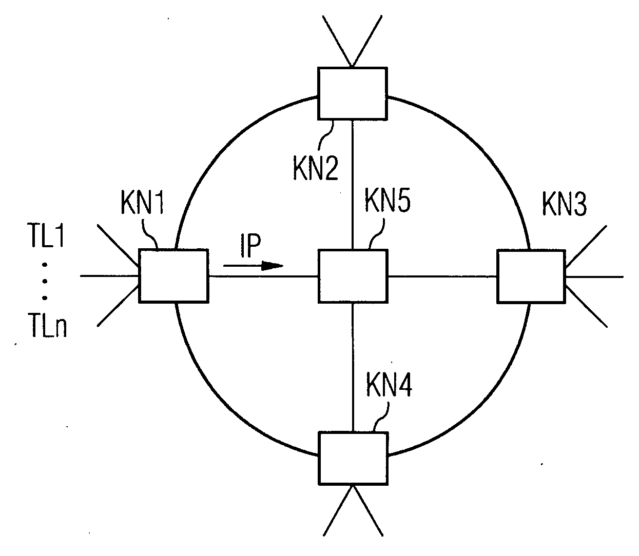
[0025]In FIG. 1, a transmission network with multiple network nodes NK1 to NK5 is shown. From subscribers who are connected at any one time to a network node NK1, data is transmitted in the form of data packets (IP packets) to the network node, combined there into data bursts, and then transmitted to a target network node, e.g. network node NK3. For simplicity, it is assumed that the data of all subscribers who are connected to network node NK1 is to be transmitted in the same quality class.

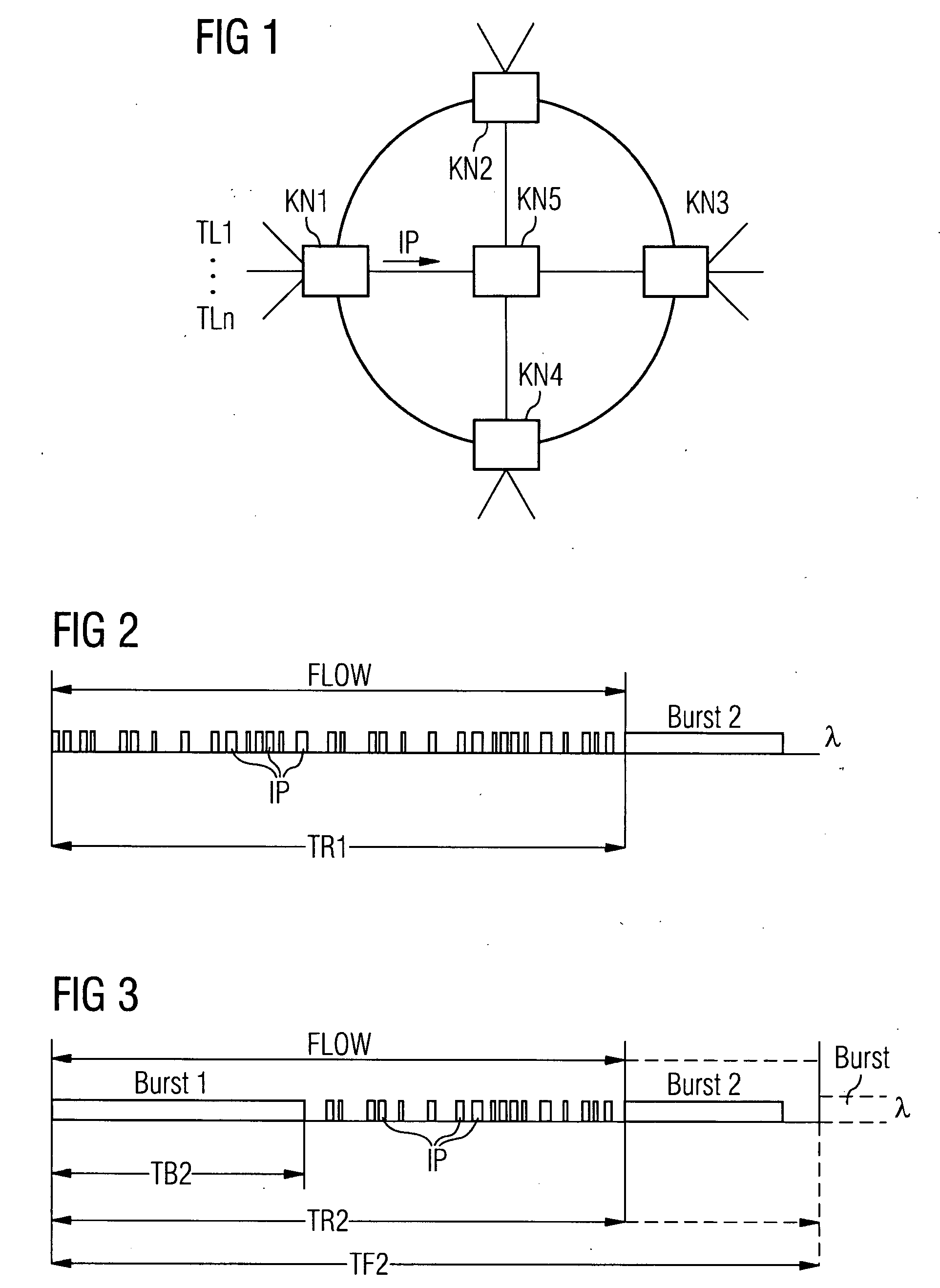
[0026]FIG. 2 shows the transmission of the data packets IP from network node NK1 in the highest (first) quality class QK1 (FIG. 6). Practically a complete transmission channel is reserved for the transmission, so that all data packets IP are sent on from network node NK1 directly, without previously being combined into data bursts. The transmission FLOW is ended only when the sending network node NK1 so determines.

[0027]In the case of multiple transmissions in the highest quality class, an attemp...


PUM


Abstract

Different transfer time periods are allocated to a network node for a connection, according to different quality classes. During the allocated transfer time period, the network node can transfer data bursts and data packets on the fly. The data packet is no longer transferred when the transfer capacity is required elsewhere.

Description

CROSS REFERENCE TO RELATED APPLICATIONS[0001]This application is the U.S. National Stage of International Application No. PCT / EP2006 / 060230, filed Feb. 23, 2006 and claims the benefit thereof. The International Application claims the benefits of German application No. 102005010918.7 DE filed Mar. 9, 2005, both of the applications are incorporated by reference herein in their entirety.FIELD OF INVENTION[0002]The invention relates to a method for transferring data packets between network nodes of an optical network, according to the independent claims.BACKGROUND OF INVENTION[0003]Data transmission via future optical networks can take place by means of so-called “optical burst switching (OBS)”. Here multiple data packets (e.g. IP packets) can be accumulated into so-called data bursts, and then sent via a data channel of a correspondingly designed optical network. The data channel corresponds to a specified wavelength of a wavelength multiplex signal (WDM / DWDM), which transmits multiple...

Claims


Application Information

Patent Timeline
IPC IPC(8): H04B10/00
CPCH04Q11/0066H04Q2011/0086H04Q2011/0084H04Q2011/0064
Inventor DE VEGA RODRIGO, MIGUEL
Owner NOKIA SIEMENS NETWORKS GMBH & CO KG
Why Eureka
Try Eureka