System for depositing food products on other food products

Inactive Publication Date: 2009-05-26
J E KARNER CO
View PDF34 Cites 0 Cited by
  • Summary
  • Abstract
  • Description
  • Claims
  • Application Information

AI Technical Summary

Benefits of technology

[0016]A controller is operatively associated with the sensor, the equipment and the upper conveyor to (1) initiate movement of the upper conveyor from a stopped condition to transport a first edible food product supported thereby and place the transported first edib

Problems solved by technology

In the modern factory production environment these practices have resulted in repetitive motion injuries to workers and significant workers compensation and medical expenses for employers.
The radical changes in velocity and direction drastically limit the type of food products and require the product to be modified by temperature and pressure to form compressed chilled portions that can accept the physical forces imposed by methods and mechanisms of prior art.
Positioned in close proximity to the filling, such sensors are costly and prone to interruption in operation due to deposits of the filling material they are intended to sense blocking the photoeyes.
The blockage of the photoeyes leads to uncontrolled portions of food product and unacceptable deposit position.
This creates rejected product and incurs downtime to identify and correct the source of the system malfunction.
Washing with chemical solutions and high pressure sprays can easily damage sensitive photoeye components resulting in improper system operation, rejected product waste, and downtime to repair.
Connectors on cables used to transmit encoder pulse information often corrode in a washdown environment and are costly and time consuming to replace.
The master controllers receiving the encoders must be located in close proximity to the encoders and therefore electronic components and circuit boards are subjected to destructive humidity and chemical vapors, must be protected from the wash water sprays and the resulting sealed enclosures require air conditioning to remove the heat generated by the controllers which would otherwise destroy themselves.
This method cannot deposit on shells spaced closer than the fixed minimum distance required to correct the position of a filling segment as it travels towards the shell.
This inability to deposit on directly adjacent shells results in the rejection and waste of the wrap and shell products.
This damage is most extreme when the blade of the food product cutter is operated or the food product pump stops after delivering its portion.

Method used


Image

  • System for depositing food products on other food products
  • System for depositing food products on other food products

Examples


Embodiment Construction

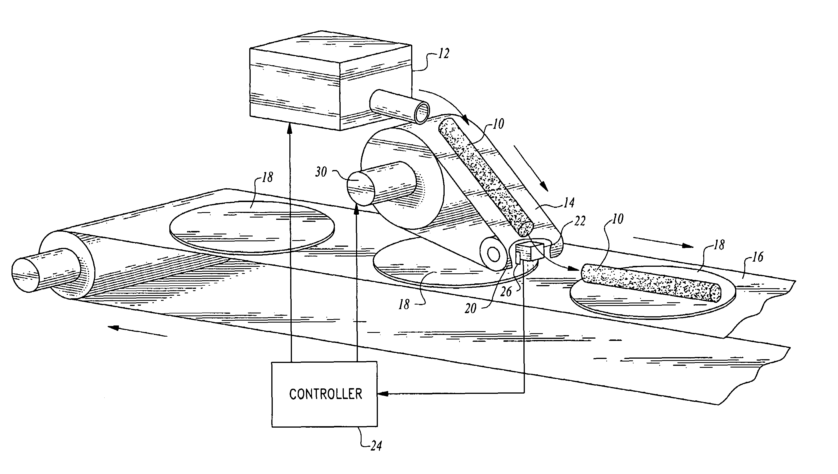
[0023]Referring now to FIG. 1, apparatus constructed in accordance with the teachings of the present invention is illustrated.

[0024]The apparatus is for serially depositing first edible food products on second edible food products. In the disclosed embodiment, the first edible food product 10 is produced or made available by a food product pump 12 which may be of any suitable commercially available type. The food product pump or equipment 12 serially makes available a plurality of the first edible food products, the latter for example being ground meat, vegetables or other material lending itself to utilization of the present invention. The first edible food products 10 produced by equipment 12 are of substantially the same length and must be so when carrying out the teachings of the present invention.

[0025]Positioned downstream from the food product pump 12 is an intermittently movable belt-type upper conveyor 14 for receiving first edible food products 10 from equipment 12 one at ...


PUM


Abstract

A first edible food product of predetermined length is received by an intermittently movable upper conveyor having an effective length the same as said predetermined length. A lower conveyor continuously transports second edible food products and a sensor senses when each of the second edible food products reaches a predetermined location. A controller receives a signal from the sensor and causes simultaneous movement of the upper conveyor to deposit the supported first edible food product and activation of equipment to place a replacement first edible food product on the upper conveyor.

Description

[0001]This application is based on and claims the benefit of U.S. Provisional Patent Application No. 60 / 477,527, filed on Jun. 10, 2003.TECHNICAL FIELD[0002]A method and apparatus for depositing first edible food products, such as fillings, on second edible food products, for example egg rolls, spring rolls, bread, cake, pastry, pizza, wraps or shells.BACKGROUND OF THE INVENTION[0003]Hand-held food products have been a regular part of the culture of man in every region of the world for thousands of years. From the egg rolls of China, burritos and enchiladas of Mexico and pizzas of the Greeks in 400 B.C., the popularity and consumption of these favorites has increased at a steady rate.[0004]Traditional products have been assembled by hand. Food products have been hand placed on a wrap or shell and folded or rolled one at a time. In the modern factory production environment these practices have resulted in repetitive motion injuries to workers and significant workers compensation and ...

Claims


Application Information

Patent Timeline
IPC IPC(8): A21D6/00A23L1/00
CPCA21C9/063A21C15/007A23L1/0073A23P1/086A23P20/20A23P30/10
InventorKARNER, JAMES E.
OwnerJ E KARNER CO