Hydraulic freewheel for an internal combustion engine with variable compression ratio
- Summary
- Abstract
- Description
- Claims
- Application Information
AI Technical Summary
Benefits of technology
Problems solved by technology
Method used
Image
Examples
Embodiment Construction
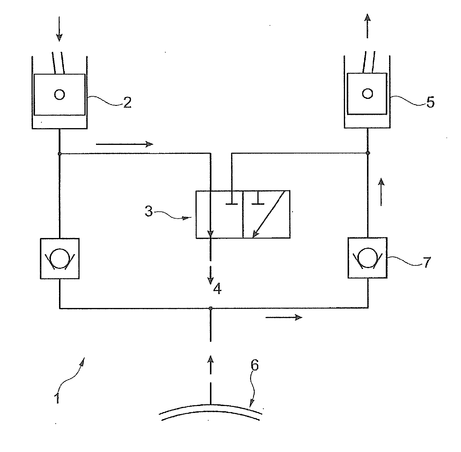
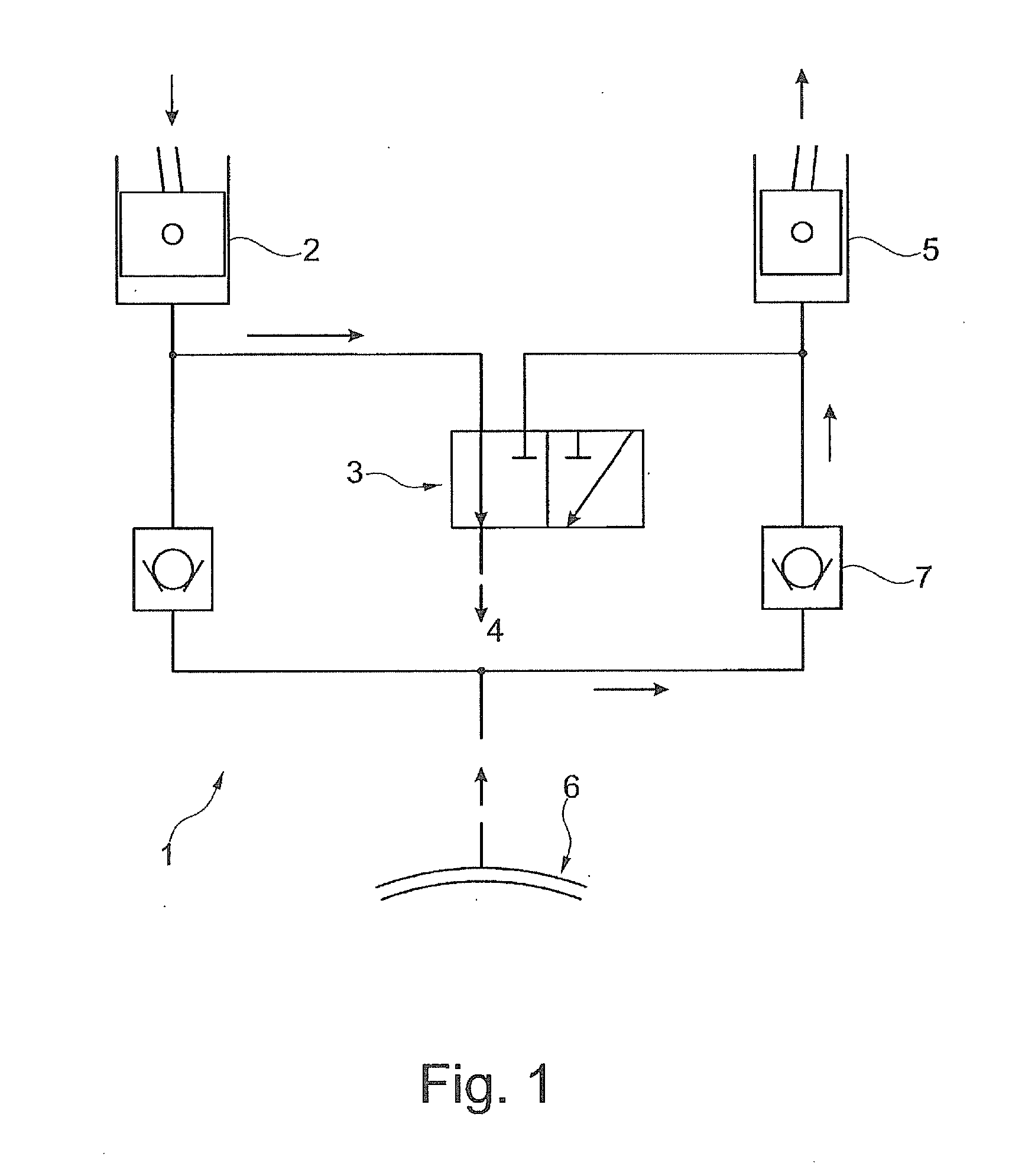
[0095]FIG. 1 shows a hydraulic freewheel with a 3 / 2-way valve, as known from DE 10 2005 055 199. In the switching position 1 illustrated, the left support piston 2 may plunge. The oil displaced from this cylinder flows via the valve 3 into the crankcase 4. The expanding support cylinder 5 draws fresh oil from the supply groove 6 via the non-return valve 7. In this arrangement, the following states exist:
a) the eccentric can rotate clockwise
b) the eccentric can rotate in a counterclockwise direction
[0096]Thus, two stable compression stages exist, so that the system may be referred to as a 2-stage VCR system. However, in operation, the VCR system may show problems as described in more detail above.
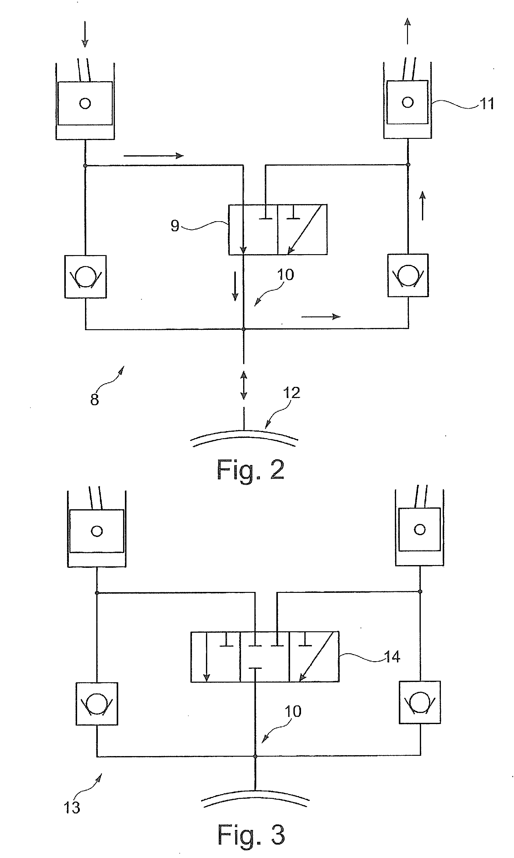
[0097]FIG. 2 shows a hydraulic diagram 8 with a 3 / 2-way valve 9 and an internal oil transfer 10. The quantity of oil displaced is used to fill the expanding support cylinder 11. Depending on the diameter ratio of the support cylinder and the lever ratios, either more oil is displaced than is...
PUM
 Abstract
Description
Claims
Application Information
 - R&D
- Intellectual Property
- Life Sciences
- Materials
- Tech Scout
- Unparalleled Data Quality
- Higher Quality Content
- 60% Fewer Hallucinations
Browse by: Latest US Patents, China's latest patents, Technical Efficacy Thesaurus, Application Domain, Technology Topic, Popular Technical Reports.
© 2025 PatSnap. All rights reserved.Legal|Privacy policy|Modern Slavery Act Transparency Statement|Sitemap|About US| Contact US: help@patsnap.com


