High frequency power amplifier

a high-frequency power amplifier and amplifier technology, applied in amplifier modifications to reduce noise influence, amplifiers with field-effect devices, solid-state devices, etc., can solve problems such as unstable first-stage amplifiers, time-consuming and laborious changes in terminal temperature, and increase terminal costs. , to achieve the effect of small temperature dependence of gain and excellent input matching

Inactive Publication Date: 2009-01-27
RENESAS ELECTRONICS CORP
View PDF10 Cites 11 Cited by
  • Summary
  • Abstract
  • Description
  • Claims
  • Application Information

AI Technical Summary

Benefits of technology

[0008]However, a process of acquiring the data of the temperature dependence of PG (Amplifier Gain) at the time of inspection of the communication terminal and recording it in the control system of the communication terminal takes a time to change the temperature of the terminal and also increases a terminal cost. Therefore, a power amplifier of small temperature dependence of the gain is being sought.
[0009]On the other hand, as other important characteristics that are required for the power amplifier used for the high frequency mobile communication terminal, there are enumerated excellent input matching, wide-band performance that the gain deviation is equal to or less than 1 dB in a transmission band, low-noise performance, and small size.
[0016]In consideration of this, the object of this invention is to solve the above-mentioned problems and provide a wide-band, low-noise, and small-sized high frequency power amplifier that has small temperature dependence of the gain and is excellent in input matching.
[0018]According to the high frequency power amplifier of this invention, it becomes possible to provide a wide-band, low-noise, and small-sized high frequency power amplifier that has small temperature dependence of the gain and is excellent in input matching.

Problems solved by technology

However, a process of acquiring the data of the temperature dependence of PG (Amplifier Gain) at the time of inspection of the communication terminal and recording it in the control system of the communication terminal takes a time to change the temperature of the terminal and also increases a terminal cost.
First, regarding input matching, if significant mismatching arises between a first-stage amplifier and the power amplifier, the first-stage amplifier may become unstable.
Furthermore, in the case of a communication system, such as CDMA, that requires linearity, if significant mismatching arises between the first-stage amplifier and the power amplifier and electric power returns to the output of the first-stage amplifier, there may occur a case where the output of the first-stage amplifier will distort due to its effect and the linearity required for the terminal will be unable to be secured.

Method used


Image

  • High frequency power amplifier
  • High frequency power amplifier
  • High frequency power amplifier

Examples


embodiment 1

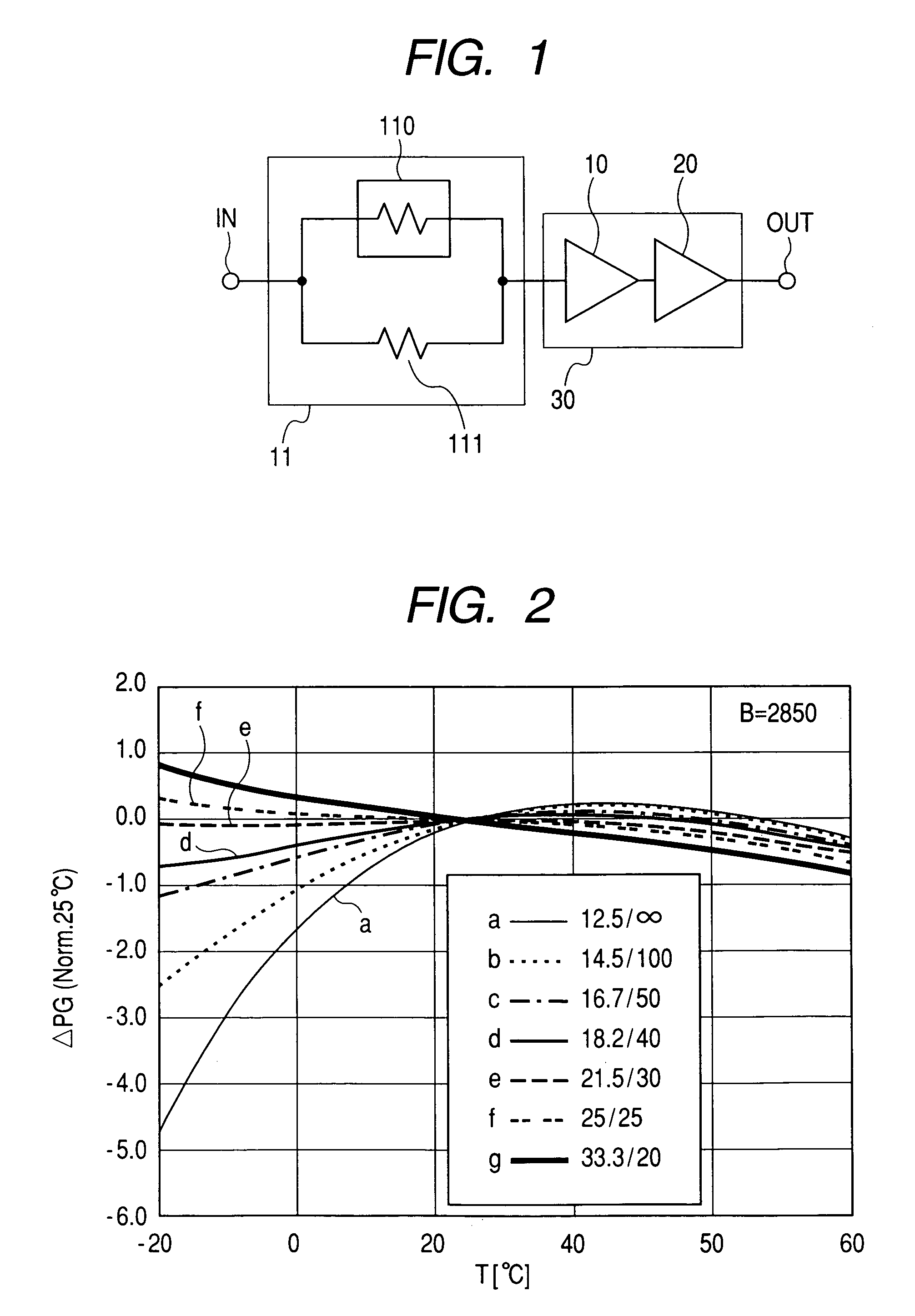
[0038]FIG. 1 is a circuit diagram showing a first embodiment of a high frequency power amplifier according to this invention. In FIG. 1, the reference numeral 30 denotes an amplifier unit, and this amplifier unit 30 is constructed in a two-stage configuration consisting of a first-stage amplifier 10 and a second-stage amplifier 20. The reference numeral 11 denotes an attenuator that is a parallel circuit consisting of a thermistor 110 having negative temperature dependence of the resistance and a resistor 111 whose temperature dependence of the resistance can be ignored in a normal operating range (hereinafter referred to as the conventional resistor). When an operating temperature range of the high frequency power amplifier was set as −20° C. to 80° C., the temperature dependence of the gain of the amplifier unit 30 was that a gain per stage of the amplifier decreased by about −2 dB almost linearly to the temperature in a high temperature side, and the temperature dependence of the...

embodiment 2

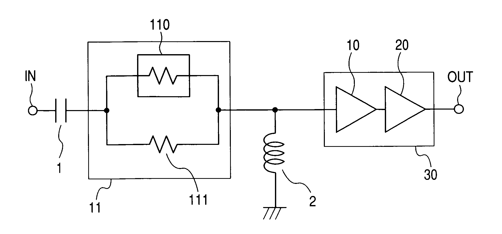
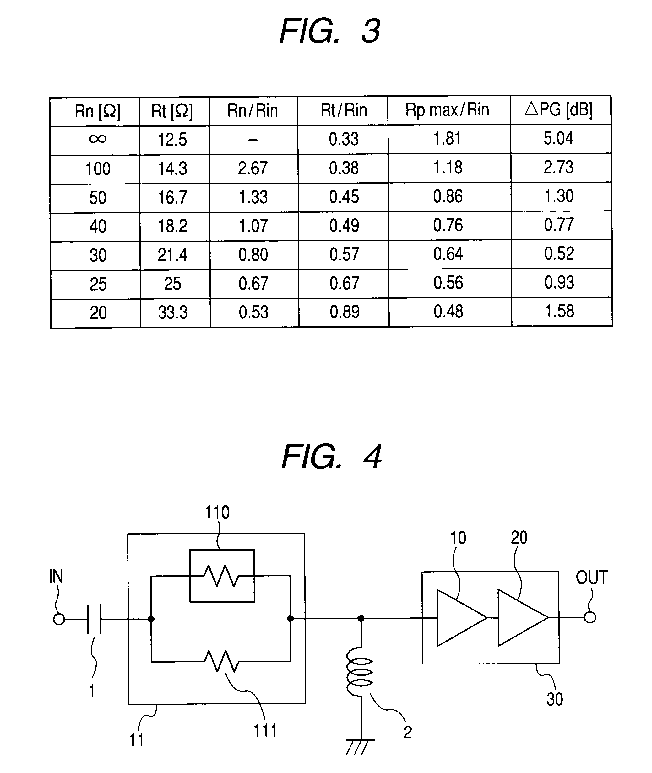
[0056]FIG. 4 is a circuit diagram showing a second embodiment of a high frequency power amplifier according to this invention. This embodiment differs from Embodiment 1 shown in FIG. 1 in that a series capacitor 1 is provided between the attenuator 11 consisting of the parallel resistors and the input terminal IN and an inductor 2 connected parallel between the attenuator 11 and the amplifier unit 30 is provided. The series capacitor 1 and the parallel inductor 2 constitute an input matching circuit of the amplifier along with the parallel resistor attenuator 11.

[0057]A situation of the matching will be described using the Smith chart of FIG. 5. An impedance when viewing the amplifier unit 30 from its input side is represented by A. The parallel inductor 2 converts the impedance on an equi-admittance circle and the impedance when viewing the amplifier side from a junction point of the parallel inductor 2 and the parallel resistor attenuator 11 becomes B.

[0058]Next, the parallel resi...

embodiment 3

[0068]FIG. 9 is a circuit diagram showing a third embodiment of a high frequency power amplifier according to this invention. In this embodiment, a parallel capacitor 4 and a series inductor 5 are provided in-stead of the parallel inductor 2 in FIG. 7. Other reference numerals are the same as those of other figures. The parallel capacitor 4 and the series inductor 5 along with the parallel resistor attenuator 11 constitute an input matching circuit of the amplifier unit. The situation of the matching is explained using the Smith chart of FIG. 10. An impedance when viewing the amplifier unit 30 from the input side is represented by A. The series inductor 5 converts the impedance on an equi-resistance circle, an impedance when viewing the amplifier unit 30 side from a junction point of the series inductor 2 and the parallel resistor attenuator 11 becomes E.

[0069]Next, the parallel resistor attenuator 11 converts the impedance on an equi-reactance circuit, so that an impedance when vie...


PUM


Abstract

The invention provides a wide-band, low-noise, and small-sized high frequency power amplifier that has small temperature dependence of the gain and is excellent in input matching. A parallel circuit consisting of a resistor whose resistance depends strongly on temperature and a conventional resistor is inserted serially into a signal path in an input matching circuit of an amplification unit, and resistances of the resistors are set to appropriate values, for example, about 2 / 3 times an input impedance of the amplification unit.

Description

CLAIM OF PRIORITY[0001]The present application claims priority from Japanese applications JP 2004-286456 filed on Sep. 30, 2004, and JP 2005-223892 filed on Aug. 2, 2005, the contents of which are hereby incorporated by reference into this application.FIELD OF THE INVENTION[0002]This invention relates to a high frequency power amplifier used for terminals for high frequency mobile communications, and more specifically, to a high frequency power amplifier whose temperature dependence of the gain is reduced.BACKGROUND OF THE INVENTION[0003]As this kind of the conventional example, JP-A No. 031746 / 2000 (Patent document 1) discloses a temperature compensation-type amplifier such that a parallel-type resistor attenuator consisting of a resistor and a thermistor is provided on the input side of an n-stage amplifier, and an isolator and / or an adjustment circuit is provided on the input side.[0004]Moreover, as another conventional example, JP-A 220334 / 1999 discloses a semiconductor circuit ...

Claims


Application Information

Patent Timeline
Patent Type & Authority Patents(United States)
IPC IPC(8): H03F3/04
CPCH03F1/26H03F1/42H03F3/04H03F3/195H03F2200/36H01L2924/0002H01L2924/00
Inventor TANOUE, TOMONORIOHNISHI, MASAMI
Owner RENESAS ELECTRONICS CORP
Why Eureka
Try Eureka