Detector for proximity sensor and proximity sensor

Inactive Publication Date: 2010-10-14
PANASONIC CORP
View PDF11 Cites 11 Cited by
  • Summary
  • Abstract
  • Description
  • Claims
  • Application Information

AI Technical Summary

Benefits of technology

[0006]According to a detector for a proximity sensor according to the present invention including: one or more of sensing portions, each of the sensing portions including at least one pair of sensing coils which has central axes along a direction intersecting with a moving direction of a sensed object moving in a predetermined moving path and is provided so as to interpose the moving

Problems solved by technology

As a result, when a relatively expensive material was used for the conductor wire in order to improve a sensing sensitivity, a problem to

Method used


Image

  • Detector for proximity sensor and proximity sensor
  • Detector for proximity sensor and proximity sensor
  • Detector for proximity sensor and proximity sensor

Examples


Example

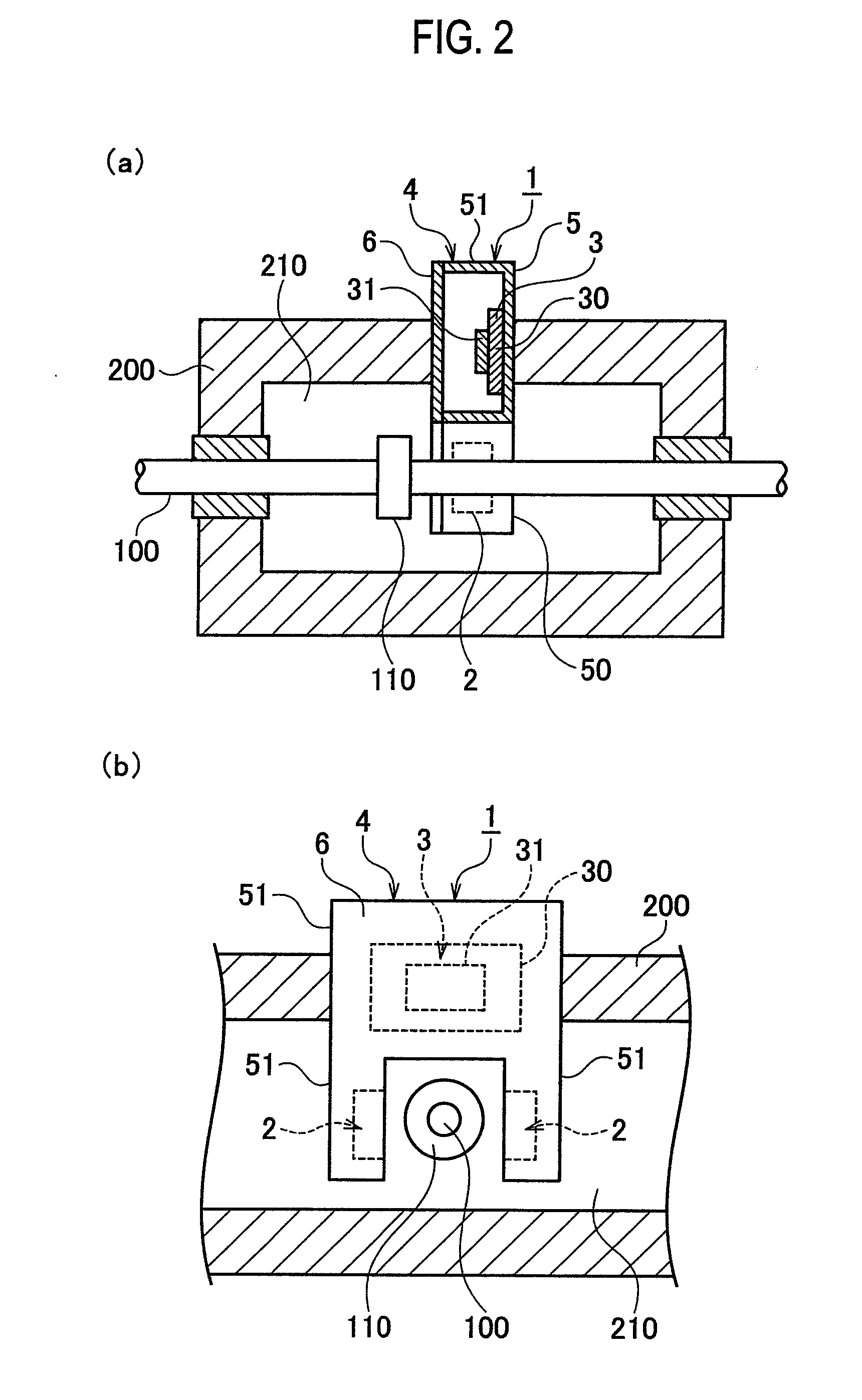
[0014]A proximity sensor in a first embodiment of the present invention is used, for example, for detecting whether a linear solenoid valve used for a hydraulic controller of an automatic transmission of a vehicle and the like operates normally or not. As illustrated in FIGS. 2(a) and 2(b), for example, the hydraulic controller includes a device main body 200 provided with a flow path 210 of driving oil (not illustrated), and is provided with a movable body 100 in the flow path 210 of the device main body 200. The movable body 100 is provided with a sensed object 110 concurrently moved with the movable body 100. The sensed object 110 has a disk-like shape having a radius larger than a radius of the movable body 100 (i.e. a cross section in the surface configured to have a different shape from a cross section of the movable body 100), and a central axis thereof is configured to have a corresponding shape to a central axis of the movable body 100. Note that, both of the movable body 1...

Example

Second Embodiment

[0035]A proximity sensor according to the present embodiment has a different configuration of a detector 1 for the proximity sensor, especially in coil blocks 2 and a housing 4, from the first embodiment, as illustrated in FIG. 5. The other configuration is the same as the first embodiment, and the explanation thereof is omitted.

[0036]Each of the coil blocks 2 according to the present embodiment includes a support substrate 24 composed of a flexible substrate having flexibility, for example. A sensing coil 20 according to the present embodiment is composed of conductor pattern formed on the support substrate 24. Each of the coil blocks 2 according to the present embodiment does not include the connection terminals 22 and 23 according to the first embodiment. Connection terminals 22 and 23 according to the present embodiment are inserted into the main body 51 of the body 5. The first connection terminal 22 according to the present embodiment is made of a conductive m...

Example

Third Embodiment

[0045]The proximity sensor according to the present embodiment has a different configuration of a detector 1 for the proximity sensor, especially in coil blocks 2 and a housing 4, from the second embodiment, as illustrated in FIGS. 6 and 7. The other configuration is the same as the second embodiment, and the explanation thereof is omitted.

[0046]Each of the coil blocks according to the present embodiment includes a rectangular-shaped support substrate 24 such as a glass epoxy substrate as illustrated in FIG. 6. The sensing coil 20 according to the present embodiment is composed of conductor patterns formed on the substrate 24 (in FIG. 6, some parts of the conductor patterns composing the sensing coil 20 are omitted for ease of illustration). One end of the sensing coil 20 is provided with a first pad 20a used for connecting with the first connection terminal 22, and the other end of the sensing coil 20 is provided with a second pad 20b used for connecting with the fi...


PUM


Abstract

A detector for a proximity sensor, includes: a sensing portion including a pair of sensing coils which has central axes along a direction intersecting with a moving direction of a sensed object moving in a predetermined moving path and is provided so as to interpose the moving path; a circuit block including a capacitor composing an LC resonant circuit with the sensing coils of the sensing portion and provided with an oscillator which oscillates the LC resonant circuit; and an electric connector composed of first connection terminals and a first conductor pattern that connect the sensing coils of the sensing portion in series, and second connection terminals and a second conductor pattern that connect the sensing coils to the oscillator.

Description

TECHNICAL FIELD[0001]The present invention relates to a detector for a high-frequency oscillation type proximity sensor and a proximity sensor using the same.BACKGROUND ART[0002]Conventionally, as a non-contact proximity sensor for sensing a sensed object made of metals (conductive materials), magnetic materials, and the like, a high-frequency oscillation type proximity sensor has been suggested. The high-frequency oscillation type proximity sensor includes an LC resonant circuit composed of a parallel circuit of a sensing coil and a capacitor. The proximity sensor senses a sensed object by use of a phenomenon that an eddy current loss is occurred due to an electromagnetic induction effect so as to change in conductance (impedance) of the sensing coil, when the sensed object is close to the sensing coil composing the LC resonant circuit. In other words, when the conductance of the sensing coil is changed, an oscillation condition of the LC resonant circuit is also changed. Thus, the...

Claims


Application Information

Patent Timeline
IPC IPC(8): G01R27/28
CPCH03K17/9505H03K17/9542H05K1/147H05K2201/105H05K1/18H05K3/3447H05K2201/1003H05K1/165
Inventor NIWA, MASAHISATAWARATSUMIDA, SUKOYA
Owner PANASONIC CORP
Why Eureka
Try Eureka