Trapezoidal shaped magnet flux intensifier motor pole arrangement for improved motor torque density

a magnet flux and intensifier technology, applied in the direction of windings, magnetic circuit rotating parts, magnetic circuit shapes/forms/construction, etc., can solve the problems of poor utilization of magnetic materials or magnets, no useful magnetic field, and large leakage flux, so as to improve torque and power characteristics, improve the utilization of motor space, and reduce the amount of leakage flux

Inactive Publication Date: 2005-04-12
CURTISS WRIGHT ELECTRO MECHANICAL
View PDF16 Cites 62 Cited by
  • Summary
  • Abstract
  • Description
  • Claims
  • Application Information

AI Technical Summary

Benefits of technology

In accordance with at least one preferred embodiment, the present invention provides a permanent magnet synchronous machine with improved torque and power characteristics. A circumferential-oriented or spoke-type rotor assembly is used with alternating permanent magnets and magnetic pole pieces. In order to reduce the amount of leakage flux in the rotor, especially at the base or lower edge of the permanent magnets (rotor shaft side), a trapezoidal or otherwise tapered permanent magnet structure is used.
By alternating trapezoidal permanent magnets and magnetic pole pieces, there is a better utilization of the space in the motor. Specifically, there is a higher intensity magnetic field created in the air gap utilizing the same radial space in the motor without altering the weight or volume of the machine. In essence, relatively unused rotor material in the rotor pole is replaced with the flux producing permanent magnets.
In theory, the iron rotor poles in the rotor of the PM synchronous machine may be tapered to a point, but the realities of affixing the poles to the rotor shaft require some horizontal dimension in most applications. Analysis has shown that providing trapezoidal permanent magnets in which the stator-side length is at least 25% greater than the rotor-side length is beneficial in providing a substantially stronger magnetic field in the air gap.
Further, the trapezoidal permanent magnet orientation of the present invention is preferably used in combination with shaped iron pole pieces, which reduces the vibration and harmonics of the motor thereby advantageously affecting the acoustic properties of the motor (less noise). Power density and good acoustic performance are typically inversely related (because the acoustically beneficial iron is heavy). The present invention addresses the issue by providing an increase in motor power density while maintaining excellent acoustic properties.

Problems solved by technology

One drawback of the circumferential as compared to the radial-oriented magnet arrangement is that the leakage flux is comparatively larger, as shown in FIG.
This leakage flux is that magnetic flux which does not cross the air gap and link the stator winding, thus providing no useful magnetic field.
However, a disadvantage of the conventional spoke circumferential topology as compared to the surface mounted radial magnet design is its poorer utilization of the magnetic material or magnets.
The high proportion of leakage flux limits the torque production; it takes a greater volume of magnetic material to produce a given amount of torque.
1(A) because the high proportion of leakage flux limits torque production.
Therefore, the surface mounted (radial) magnet topology can give the required electromagnetic torque with less leakage and thus, a smaller magnet volume than the spoke (circumferential) design, but the radial design is less desirable in several applications when torque harmonics, acoustic performance, permanent magnet surface eddy current losses, and resistance to demagnetization are considered.

Method used


Image

  • Trapezoidal shaped magnet flux intensifier motor pole arrangement for improved motor torque density
  • Trapezoidal shaped magnet flux intensifier motor pole arrangement for improved motor torque density
  • Trapezoidal shaped magnet flux intensifier motor pole arrangement for improved motor torque density

Examples


Embodiment Construction

It is to be understood that the figures and descriptions of the present invention have been simplified to illustrate elements that are relevant for a clear understanding of the invention, while eliminating, for purposes of clarity, other elements that may be well known. Those of ordinary skill in the art will recognize that other elements are desirable and / or required in order to implement the present invention. However, because such elements are well known in the art, and because they do not facilitate a better understanding of the present invention, a discussion of such elements is not provided herein. The detailed description will be provided hereinbelow with reference to the attached drawings.

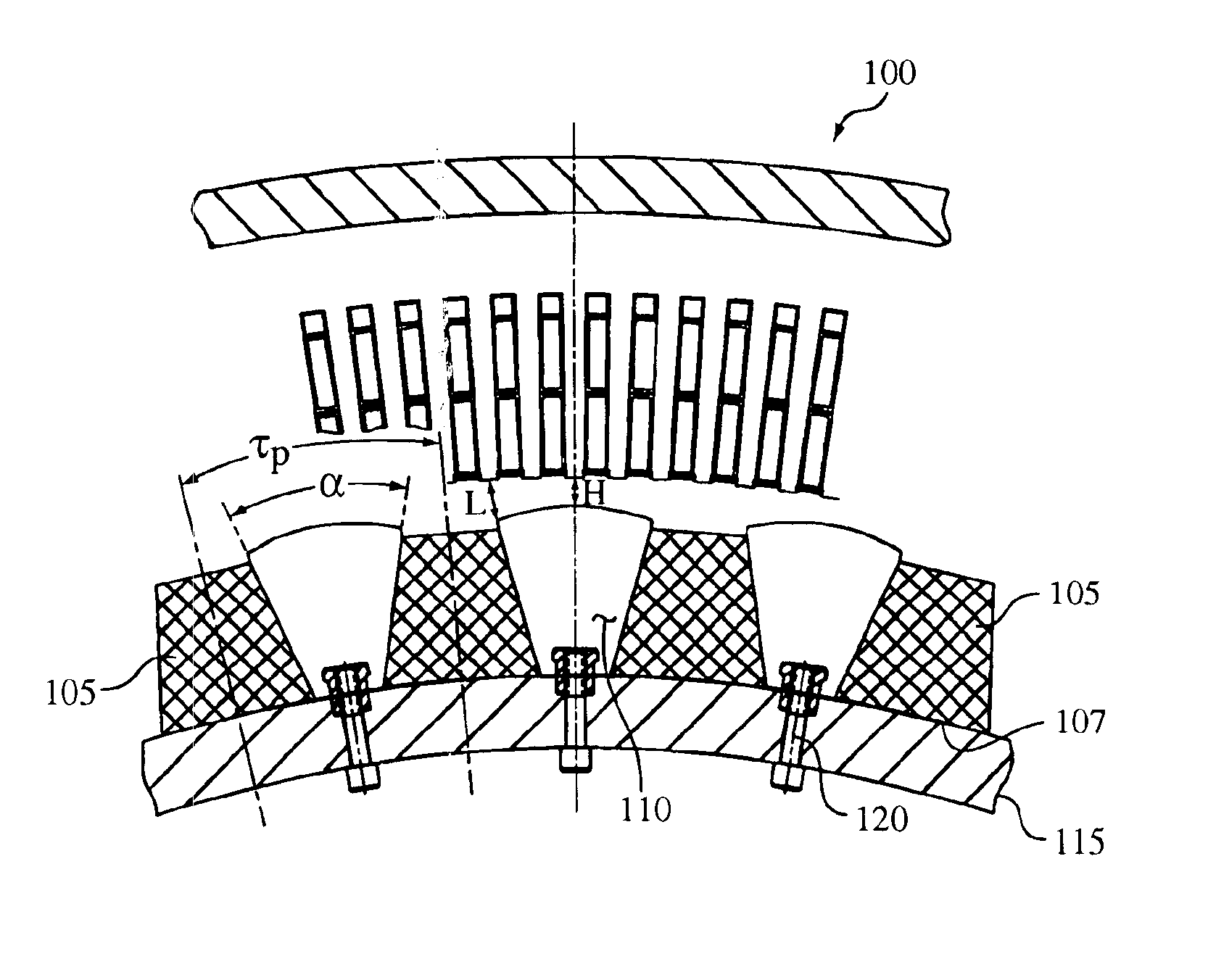
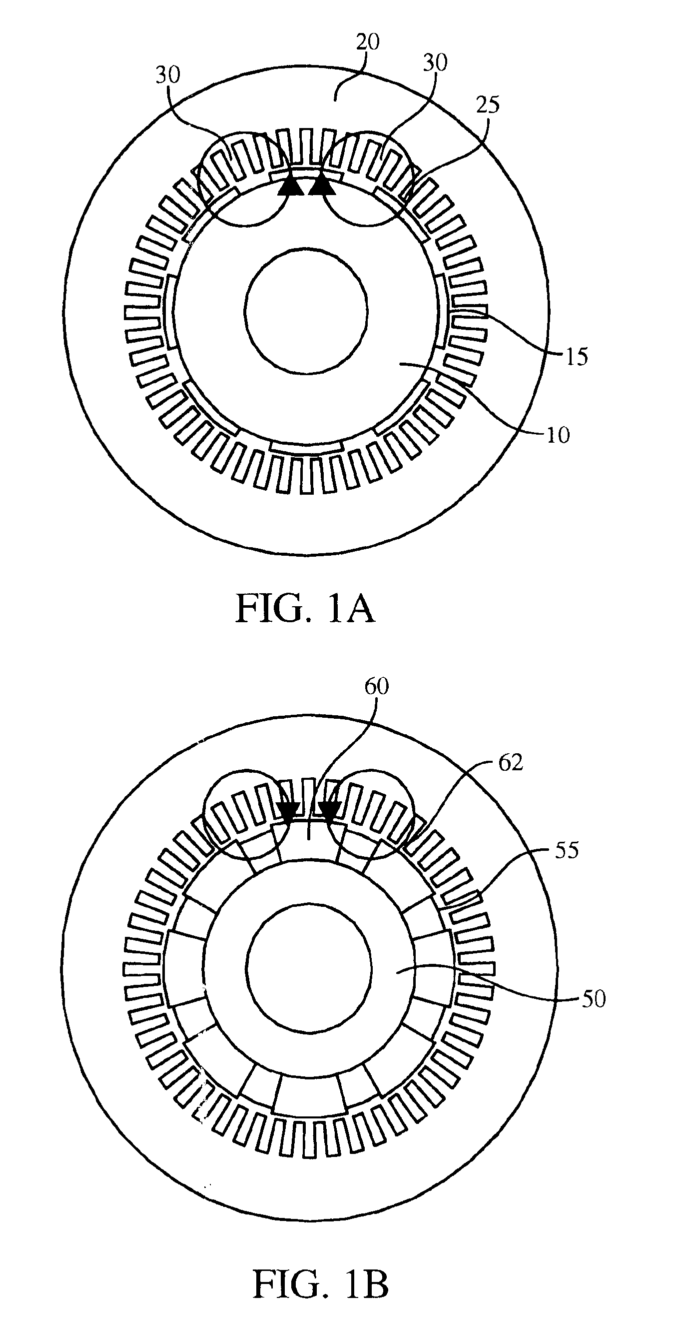
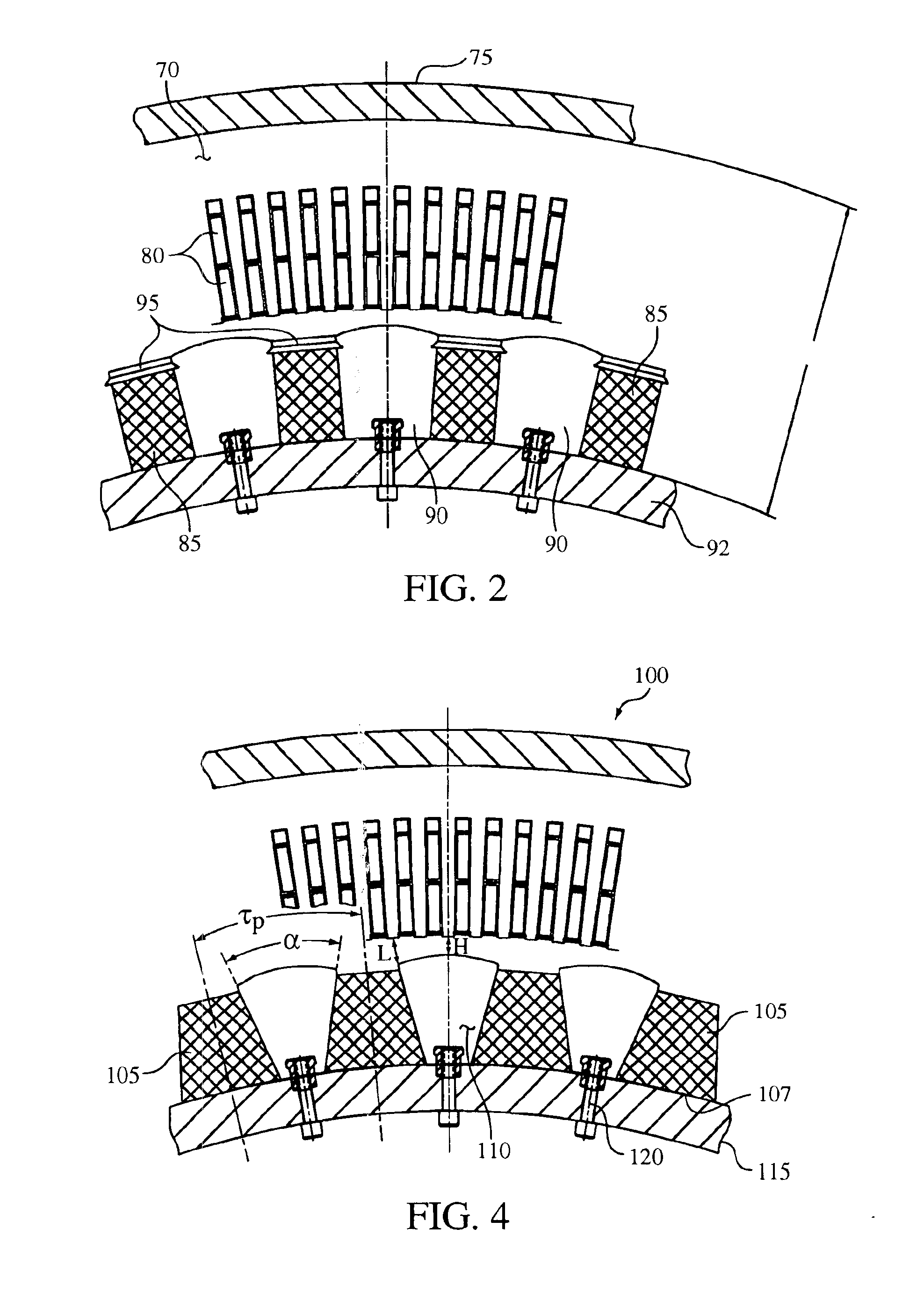
By altering the shape of the permanent magnets in a circumferential-oriented synchronous machine, the leakage flux may be reduced, thereby improving the torque or power density of the machine by increasing flux density across the air gap. In order to better understand the reasons for the sh...


PUM


Abstract

A permanent magnet synchronous machine with improved torque and power characteristics. A circumferential-oriented rotor assembly is provided with alternating permanent magnets and magnetic pole pieces. In order to reduce the amount of leakage flux in the rotor and increase the effective length of the permanent magnet, a trapezoidal or otherwise tapered permanent magnet structure is used. By alternating trapezoidal permanent magnet, and magnetic pole pieces, a higher intensity magnetic field is created in the air gap utilizing the same radial space in the motor without altering the weight or volume of the motor compared to conventional machines.

Description

BACKGROUND OF THE INVENTION1. Field of the InventionThe present invention relates generally to synchronous machines, and, more specifically, the present invention is directed to permanent magnet synchronous machines with improved torque and / or power density characteristics.2. Description of the BackgroundRecent advancements and applications of at least three technologies—microprocessors, power semiconductors and rare earth permanent magnets—has significantly contributed to the development of permanent magnet synchronous motors. Permanent magnet motors are typically characterized by the distinct advantages of simple construction, high efficiency, high power factor, and high power density. These types of motors are therefore well suited to ship and other vehicle propulsion systems.As the size and weight of vehicles has rapidly increased, the development of advanced propulsion systems has inherently involved the design and construction of advanced large power, low speed propulsion moto...

Claims


Application Information

Patent Timeline
Patent Type & Authority Patents(United States)
IPC IPC(8): H02K1/27
CPCH02K1/2766
Inventor CALFO, RAYMOND MARKKREFTA, MARK PETER
Owner CURTISS WRIGHT ELECTRO MECHANICAL
Why Eureka
Try Eureka