Digital cameras with triangulation autofocus systems and related methods

a digital camera and triangulation technology, applied in the field of digital camera devices, can solve the problems of affecting so as to achieve the effect of improving the accuracy of the imag

Inactive Publication Date: 2009-05-26
SONY ERICSSON MOBILE COMM AB
View PDF13 Cites 20 Cited by
  • Summary
  • Abstract
  • Description
  • Claims
  • Application Information

AI Technical Summary

Benefits of technology

[0011]In some embodiments the methods can include automatically stabilizing the focus of a moving subject in a still image using the captured spot image. The projecting step may include emitting light from a light source in a visible part of a light spectrum.
[0027]The digital camera may include a control circuit that is configured to selectively operate the camera in a still image camera mode and in a video recording mode. The control circuit may be configured to control emission of a spot beam pulse during the still image and video recording modes, and the control circuit may be configured to prevent emission of the spot beam pulse during acquisition of selected images.

Problems solved by technology

It is believed that the auto focus actions for an image using these devices is relatively slow can take about 1-2 seconds to perform.
Unfortunately, while sub-sampling may shorten the auto focus time, a degradation in precision may be introduced.
In addition, the time it takes to focus is still relatively long, typically about 1 second.
This may make it difficult to achieve a good tracking auto focus for video recording using the sub-sampling technique.
However, it is difficult to determine how much the subject has moved and / or in which direction.
Some relatively sophisticated and precise (relatively expensive) video systems may address this problem by “hunting” the lens back and forth in very small steps.

Method used


Image

  • Digital cameras with triangulation autofocus systems and related methods
  • Digital cameras with triangulation autofocus systems and related methods
  • Digital cameras with triangulation autofocus systems and related methods

Examples


Embodiment Construction

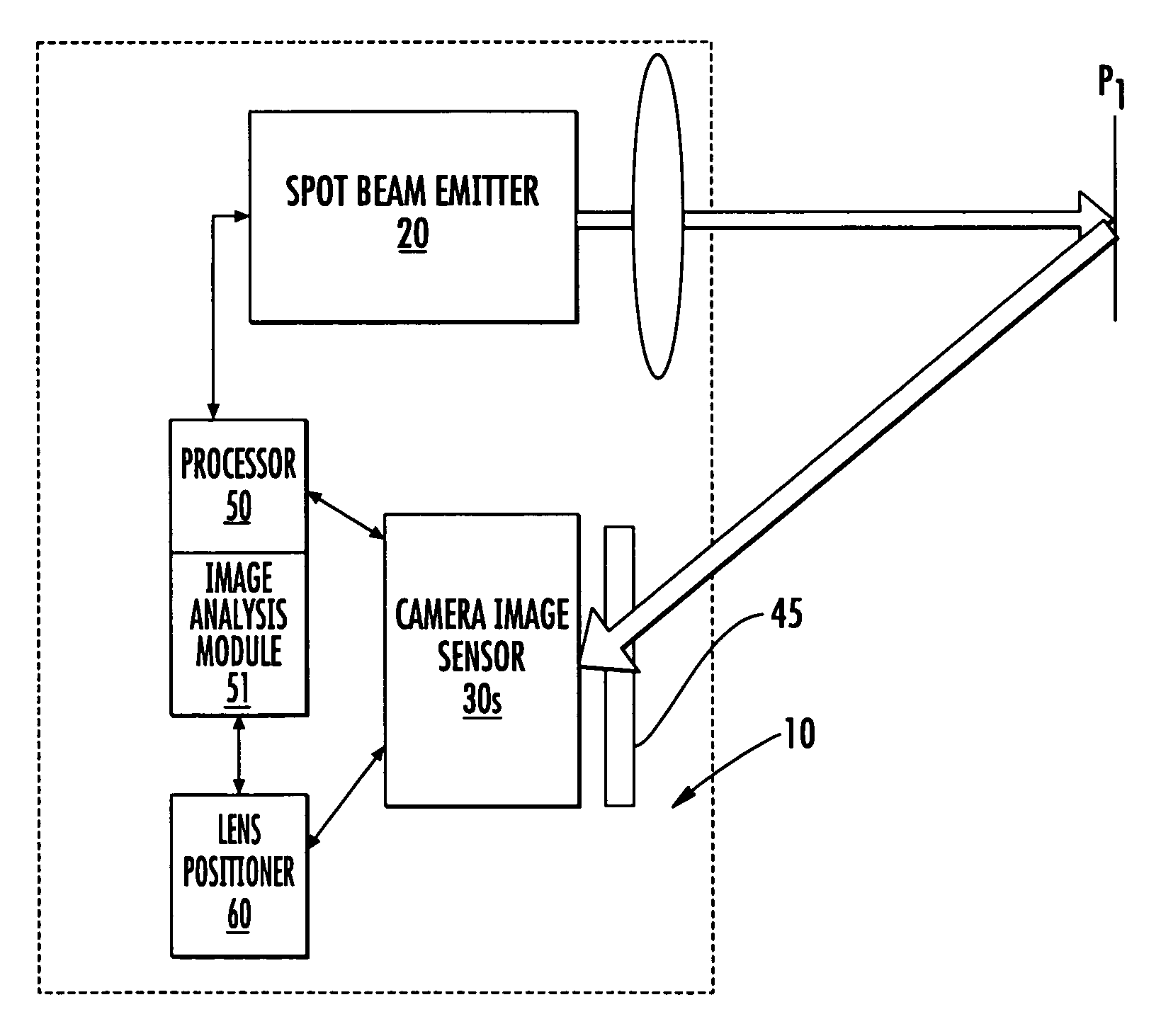
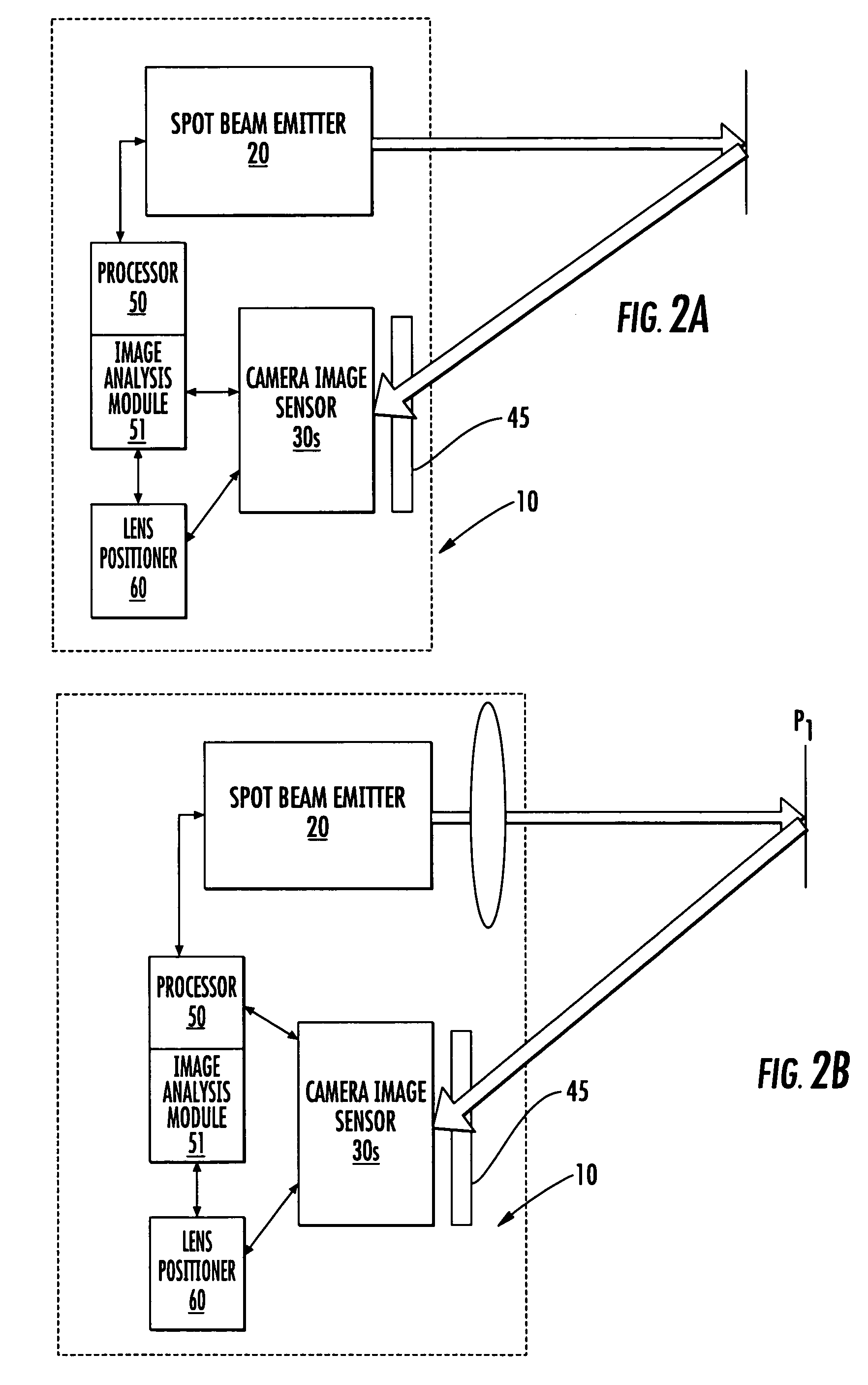
[0007]Some embodiments of the present invention provide digital cameras with triangulation auto focus systems. Certain embodiments of the present invention provide mobile communication devices incorporating digital cameras that have triangulation auto focus systems.

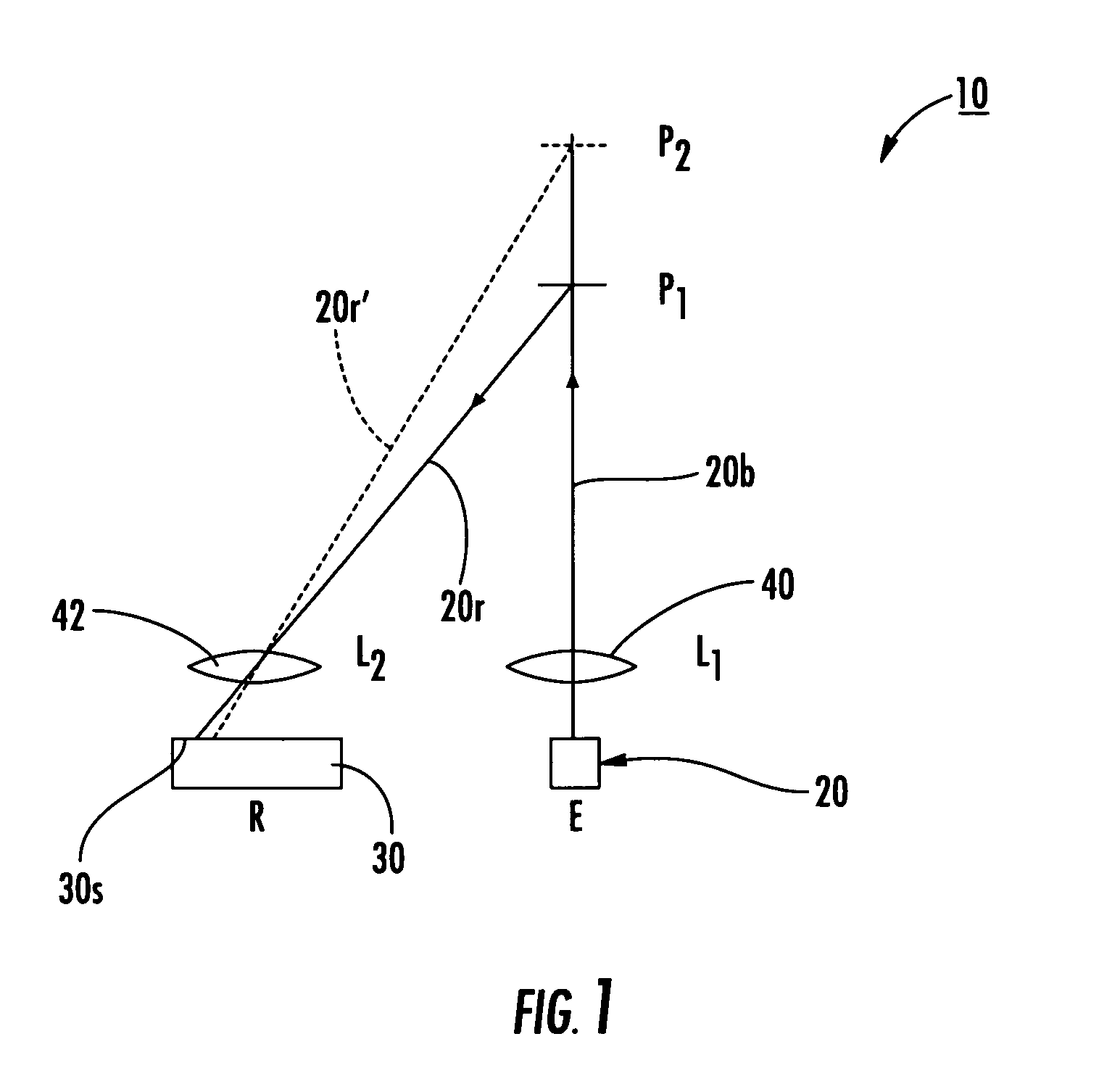
[0008]Some further embodiments of the present invention are directed to methods of auto-focusing a digital camera in still image and / or video recording mode. The methods include: (a) projecting at least one light spot toward a target subject; (b) capturing a first image of the target subject having the at least one light spot in response to the projecting step; (c) programmatically determining a distance of the target subject from the digital camera using the image with the light spot; and (d) automatically focusing a digital camera lens based on the determining step. In some embodiments, the methods can include: capturing a second image of a target subject devoid of an emitted light spot proximate in time to the capturin...


PUM


Abstract

Digital cameras with triangulation auto focus systems include a spot beam emitter than can be used to project a spot onto a subject that is captured in an image and used to electronically automatically determine a subject to camera distance.

Description

FIELD OF THE INVENTION[0001]The present invention generally relates to digital camera devices, and may be particularly suitable for mobile electronic devices that include a digital camera.BACKGROUND OF THE INVENTION[0002]Many digital still image and video cameras employ a passive type auto focus system that measures the contrast of image content. Generally described, when comparing a sharp image with a blurred image, rendered on the same scene, the sharp image contains more information from high spatial frequencies. There are more transitions between dark and bright areas and the difference between the dark and bright areas is greater. Assessing the contrast of image content between images can give a relative measure of sharpness. A conventional contrast-based auto focus system includes a camera lens, a focusing means for changing the position of the lens, an imaging sensor and a digital signal processor (DSP). The lens is configured to move to different discrete focusing positions,...

Claims


Application Information

Patent Timeline
Patent Type & Authority Patents(United States)
IPC IPC(8): G03B13/00H04N5/232H04N5/228
CPCH04N5/23212H04N5/23248H04N5/23254H04N5/23258H04N5/23277H04N2007/145H04N23/671H04N23/6845H04N23/6811H04N23/68H04N23/6812
Inventor WERNERSSON, MATS GORAN HENRY
Owner SONY ERICSSON MOBILE COMM AB
Why Eureka
Try Eureka