Optical apparatus with reduced effect of mirror edge diffraction

a technology of optical apparatus and mirror edge, applied in the field of optical apparatus, can solve the problems of unsatisfactory effects of the behavior of broadband amplifier, and achieve the effects of reducing the increased power level, and optimizing the passband

Active Publication Date: 2009-05-26
CAPELLA PHOTONICS INC
View PDF64 Cites 19 Cited by
  • Summary
  • Abstract
  • Description
  • Claims
  • Application Information

AI Technical Summary

Benefits of technology

[0013]The effects of diffraction and interference of a spectral beam from the edges of the micromirrors are reduced in order to optimize the passband and reduce the increased power levels between the passbands. This increased power level can cause undesirable effects from the behavior of broadband amplifiers. The undesirable effects of diffraction on the passband may be reduced by appropriate modification of the edges of the micromirrors.

Problems solved by technology

This increased power level can cause undesirable effects from the behavior of broadband amplifiers.

Method used


Image

  • Optical apparatus with reduced effect of mirror edge diffraction
  • Optical apparatus with reduced effect of mirror edge diffraction
  • Optical apparatus with reduced effect of mirror edge diffraction

Examples


Embodiment Construction

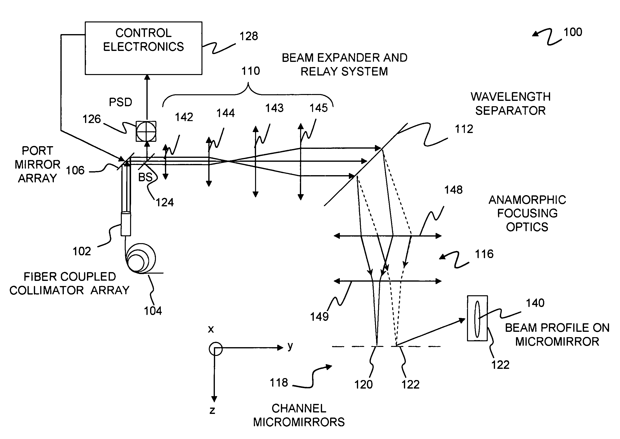
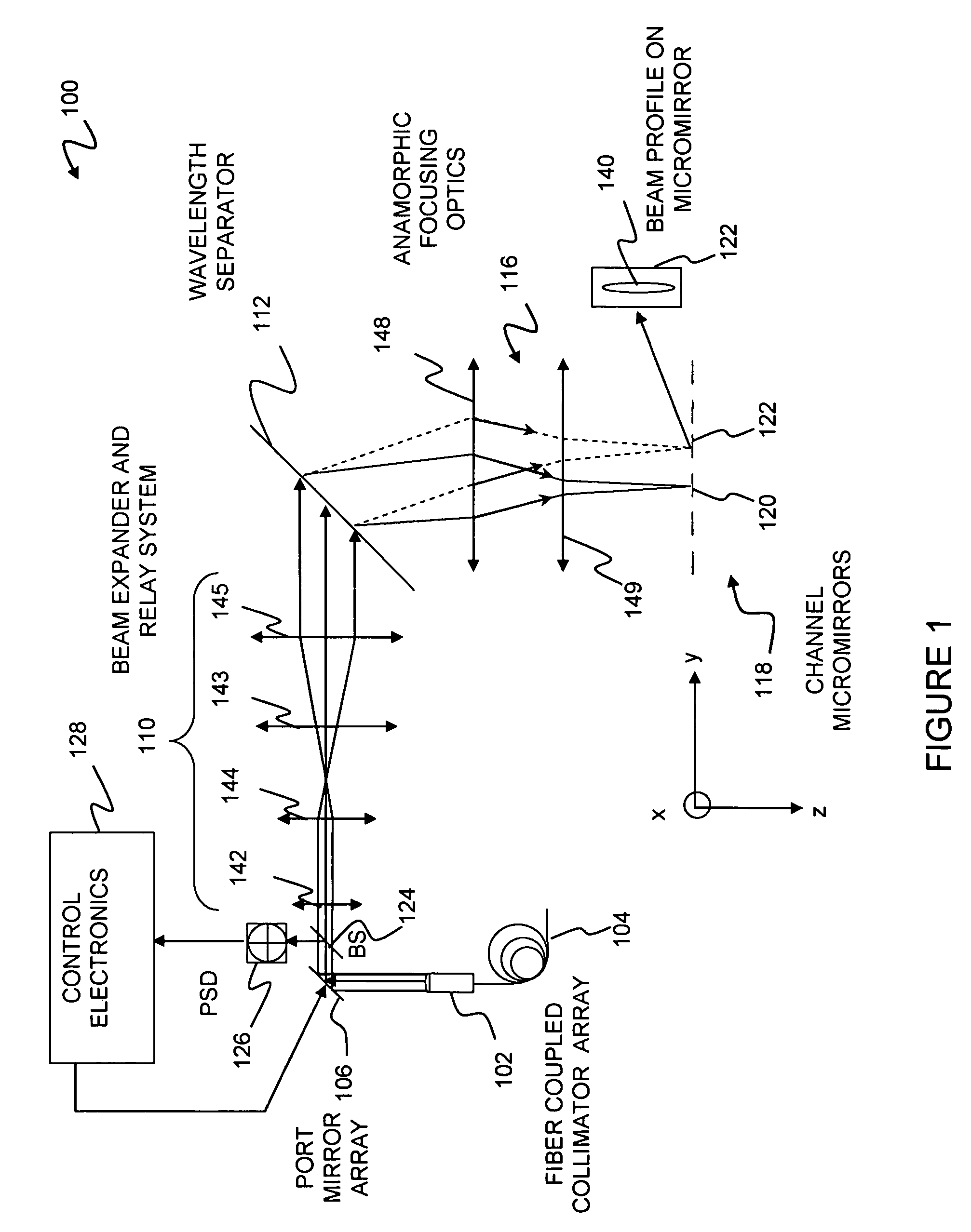
[0041]Embodiments of the present invention are particularly applicable to wavelength selective switches (WSS) as used, for example, in reconfigurable optical add-drop multiplexers (ROADM's) permitting dynamic network reconfiguration and enabling management of the power or attenuation of individual spectral channels of a multi-wavelength (multi-channel) optical signal, such that signals can be readily added to or dropped from the network. One or more components of such switches are configured to reduce passband non-uniformities due to diffraction at edges of micromirrors used to switch optical signals from one port to another. It will become apparent, however, that this is illustrative of only one utility of the invention.

[0042]FIG. 1 is a diagrammatic view that illustrates an example of an architecture of a portion of a wavelength selective switch 100 of a type that may be used in conjunction with embodiments of the present invention. One or more wavelength selective switches having...


PUM


Abstract

A micromirror for use in an optical apparatus may comprise a reflective portion, configured to be rotatable about a switching axis and an attenuation axis that is different from the switching axis. The reflective portion may include an edge that is substantially parallel to the attenuation axis. The edge may include one or more edge features that protrude above a plane of the micromirror surface and / or are submerged below the plane of the micromirror surface, and / or have an edge shape that deviates from a straight line. Alternatively, an array of micromirrors may have mirrors characterized by sawtooth features disposed along edges that are substantially parallel to the attenuation axis.

Description

CLAIM OF PRIORITY[0001]This application is a continuation-in-part of and claims the benefit of priority of commonly-assigned co-pending U.S. patent application Ser. No. 11 / 104,143, the entire contents of which are incorporated herein by reference.[0002]This application is a continuation-in-part of and claims the benefit of priority of commonly-assigned co-pending U.S. patent application Ser. No. 11 / 317,450, the entire contents of which are incorporated herein by reference.[0003]This application is a continuation-in-part of and claims the benefit of priority of commonly-assigned co-pending U.S. patent application Ser. No. 11 / 469,394, the entire contents of which are incorporated herein by reference.FIELD OF THE INVENTION[0004]Embodiments of the invention are generally related to optical communications systems and more particularly to optical apparatus that use micromirrors for switching and / or attenuation of optical signals.BACKGROUND[0005]Multi-channel optical signals typically comp...

Claims


Application Information

Patent Timeline
Patent Type & Authority Patents(United States)
IPC IPC(8): G02B6/26
CPCG02B6/29311G02B6/352G02B6/4246G02B26/0833G02B27/0911G02B6/29383G02B6/356G02B6/3594
Inventor MARTINELLI, MASSIMOYANG, LONGGARRETT, MARK H.OSTROM, ROBERTDAVIS, JOSEPH E.
Owner CAPELLA PHOTONICS INC
Why Eureka
Try Eureka