Serpentine metal gasket

a metal gasket and serpentine technology, applied in fluid pressure sealed joints, cable terminations, mechanical equipment, etc., can solve the problems of difficult removal of seals after use, relatively high cost, and relatively unreliable seals, so as to eliminate both rotation and cost.

Inactive Publication Date: 2009-06-02
JEFFERSON SCI ASSOCS LLC
View PDF4 Cites 8 Cited by
  • Summary
  • Abstract
  • Description
  • Claims
  • Application Information

AI Technical Summary

Benefits of technology

[0005]It is therefore an object of the present invention to provide a gasket or seal between cryogenic conduits that eliminates both the rotation and cost issues just described.

Problems solved by technology

Such seals have proven relatively unreliable due to the propensity of the straight portions of such generally rectangular seals to rotate as the dissimilar materials of the seals and the cryogenic conduits contract under cryogenic conditions.
This problem is not so prevalent when the cryogenic conduits being joined are round since forces exerted upon the seal are generally more balanced than in the case where the conduits have a more rectangular overall shape.
Such a solution is relatively high cost and removal of the seals after use is often very difficult.

Method used


Image

  • Serpentine metal gasket
  • Serpentine metal gasket
  • Serpentine metal gasket

Examples


Embodiment Construction

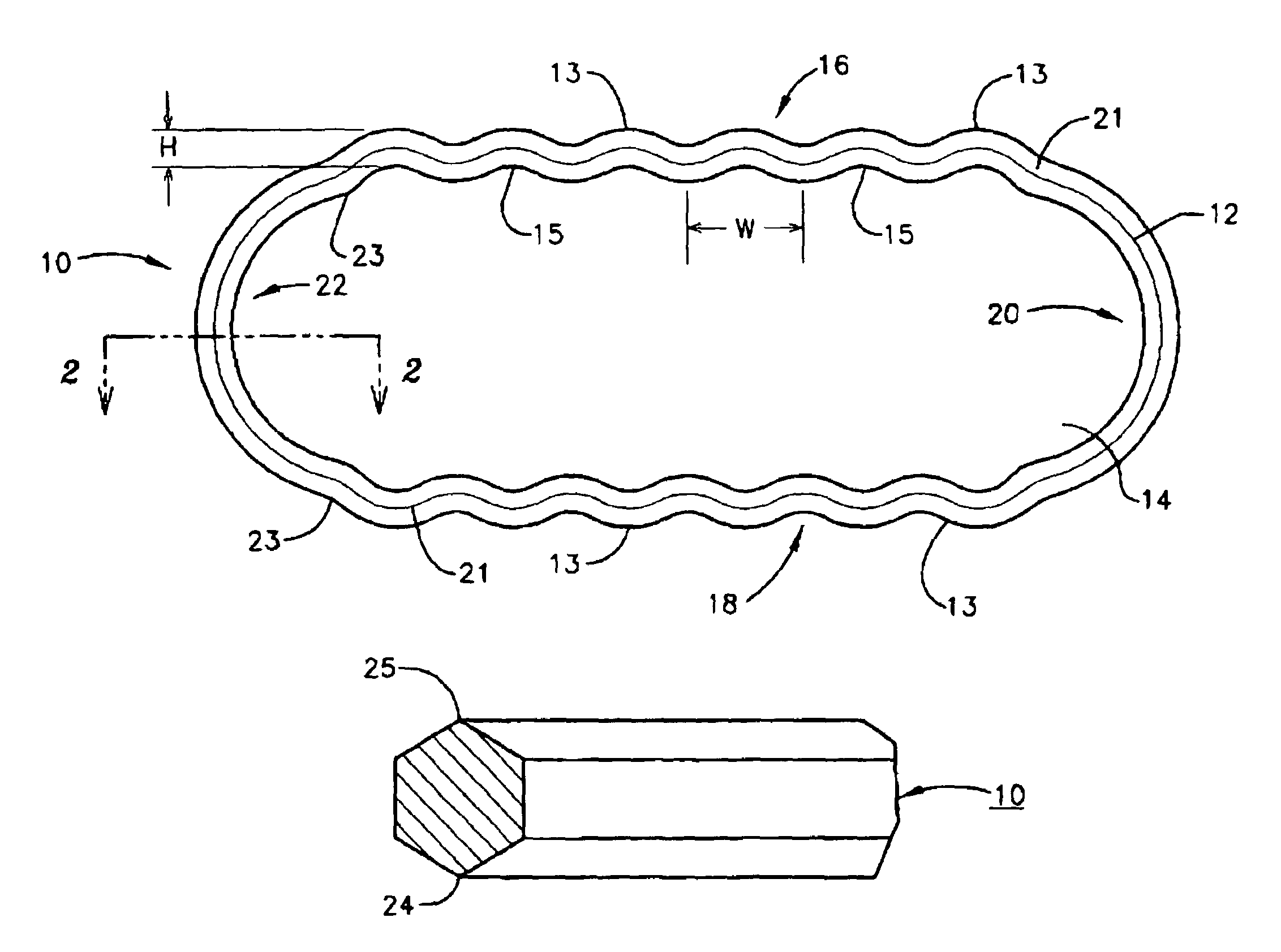
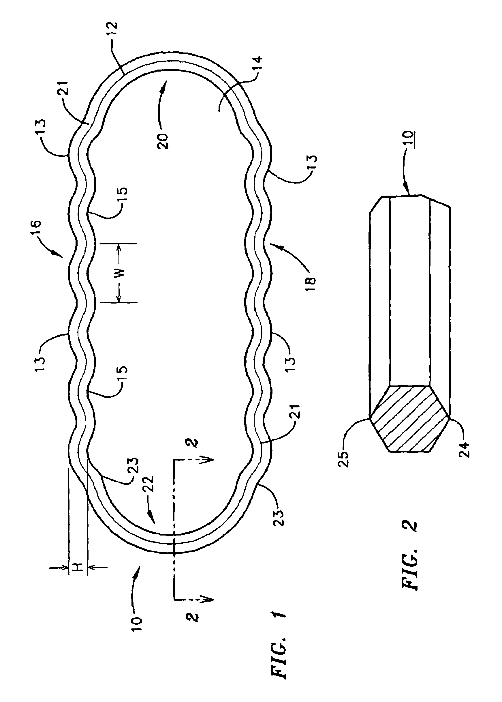
[0010]Referring now to FIG. 1, according to one preferred embodiment of the present invention, the seal or gasket 10 of the present invention comprises a periphery 12 defining a central aperture 14. According to the preferred embodiment depicted in FIG. 1, seal or gasket 10 has at least two opposing elongated sides 16 and 18 and two arcuate opposing ends 20 and 22 joining opposing elongated sides 16 and 18. Each of opposing elongated sides 16 and 18 is serpentine in shape. The term “serpentine” as used herein is meant and intended to define an oscillatory, smoothly varying shape. While according to a preferred embodiment, the waves of the serpentine shape of opposing elongated sides 16 and 18 are of uniform width W and height H as shown in FIG. 1, it will be readily apparent to the skilled artisan that the serpentine curves of opposing elongated sides 16 and 18 may be of differing widths and heights without departing from the spirit of the invention and the scope of the appended cla...


PUM


Abstract

A metallic seal or gasket for use in the joining of cryogenic fluid conduits, the seal or gasket having a generally planar and serpentine periphery defining a central aperture. According to a preferred embodiment, the periphery has at least two opposing elongated serpentine sides and two opposing arcuate ends joining the opposing elongated serpentine sides and is of a hexagonal cross-section.

Description

[0001]The United States of America may have certain rights to this invention under Management and Operating Contract DE-AC05-84ER 40150 from the United States Department of Energy.FIELD OF THE INVENTION[0002]The present invention relates to metallic gaskets for sealing joints between vacuum conducting elements of dissimilar materials and more particularly to such a gasket that is useful in cryogenic applications.BACKGROUND OF THE INVENTION[0003]In many research and commercial applications, there exists the need to provide joints between cryogenic vacuum conductive elements such as pipes and the like. Such a need is apparent in the construction and operation of, for example, particle accelerators and other superconductive experimental arrangements and apparatus. Such seals are conventionally attained through the use of a gasket or seal between flanges located on each of the vacuum conductive members. Many such fluid conductors are generally rectangular in shape for a variety of reaso...

Claims


Application Information

Patent Timeline
Patent Type & Authority Patents(United States)
IPC IPC(8): F16L17/06
CPCF16J15/0881F16L23/20Y10S285/917Y10S285/904
Inventor ROTHGEB, TIMOTHY MOOREREECE, CHARLES EDWIN
Owner JEFFERSON SCI ASSOCS LLC
Why Eureka
Try Eureka