
One-dimensional illumination apparatus and imaging apparatus

a one-dimensional illumination and imaging apparatus technology, applied in the field of one-dimensional illumination apparatus and imaging apparatus, can solve the problems of high cost, difficulty in realizing high-efficiency laser production, and output efficiency of laser light sources and the like, and achieve the effect of reducing speckle noise and high output efficiency

Inactive Publication Date: 2009-06-09
SONY CORP
View PDF9 Cites 52 Cited by
  • Summary
  • Abstract
  • Description
  • Claims
  • Application Information

AI Technical Summary

Benefits of technology

[0010]From the foregoing, it is desirable to provide a one-dimensional illumination apparatus and an imaging apparatus which are high in output and efficiency and are effective for reducing the speckle noises.

Problems solved by technology

However, the configurations according to the related art have problems as to the output and efficiency of the laser light source and the like.
For example, in application to image projectors and the like, it is desirable to use a green laser apparatus with an output of about 5 W, but it is difficult to actually produce a high-output high-efficiency laser, or the use of an expensive apparatus leads to such problems as a rise in cost.
In addition, in order to form a line beam with which to irradiate a one-dimensional light modulation device from a spot-like laser light, it is desirable to use a profile conversion optical system, a line generator or the like, which causes complication of configuration.
Besides, it may be necessary to perform an optical adjustment (alignment) with high accuracy, or the number of portions to be adjusted may be increased, resulting in an influence on stability or the like problems.
Besides, where non-uniformity in beam intensity of one-dimensional oscillation is observed, irregularities in intensity may be generated at the time of illumination.

Method used


Image

  • One-dimensional illumination apparatus and imaging apparatus
  • One-dimensional illumination apparatus and imaging apparatus
  • One-dimensional illumination apparatus and imaging apparatus

Examples


Embodiment Construction

[0050]The present invention relates to a one-dimensional illumination apparatus and an imaging apparatus which use a one-dimensional transverse multiple mode laser, and can be applied, for example, image display apparatuses (image projectors, etc.), image output apparatuses such as plotters, printers, etc., various working or processing apparatuses, and the like which use light modulation devices.

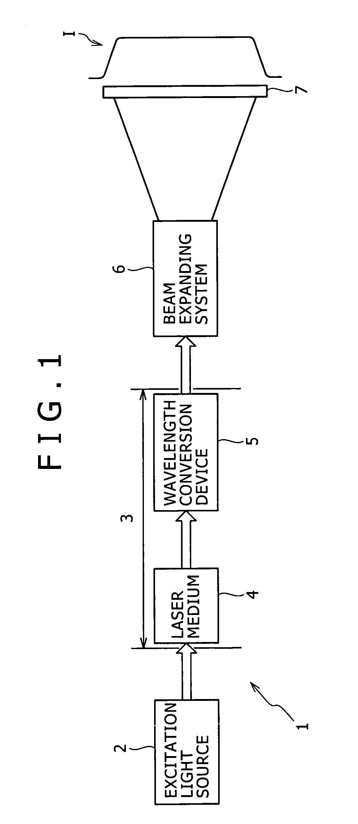
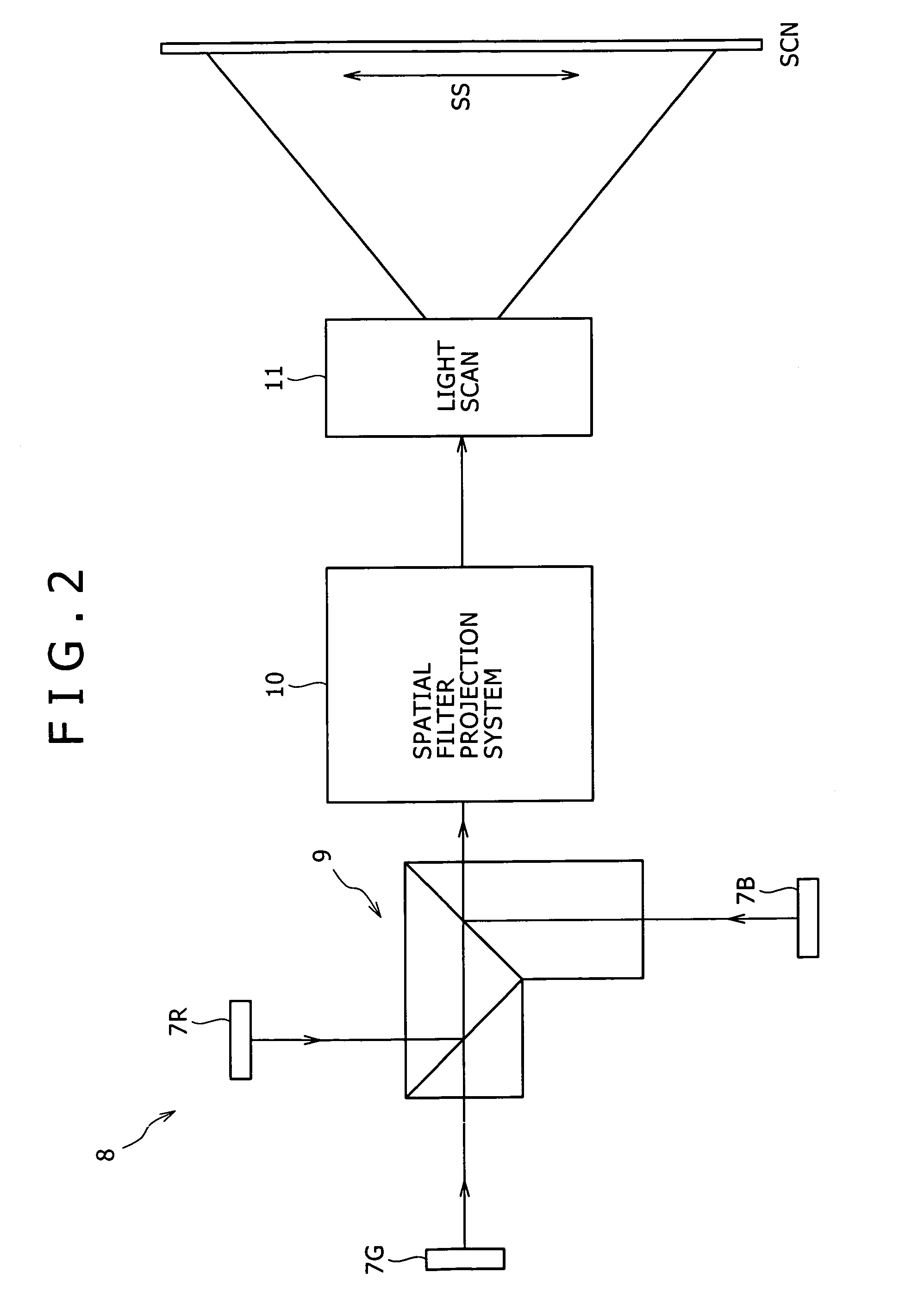
[0051]FIGS. 1 and 2 show an example of fundamental configuration according to an embodiment of the present invention.

[0052]FIG. 1 shows an exemplary configuration of a one-dimensional illumination apparatus concerning a one-dimensional light modulation device.

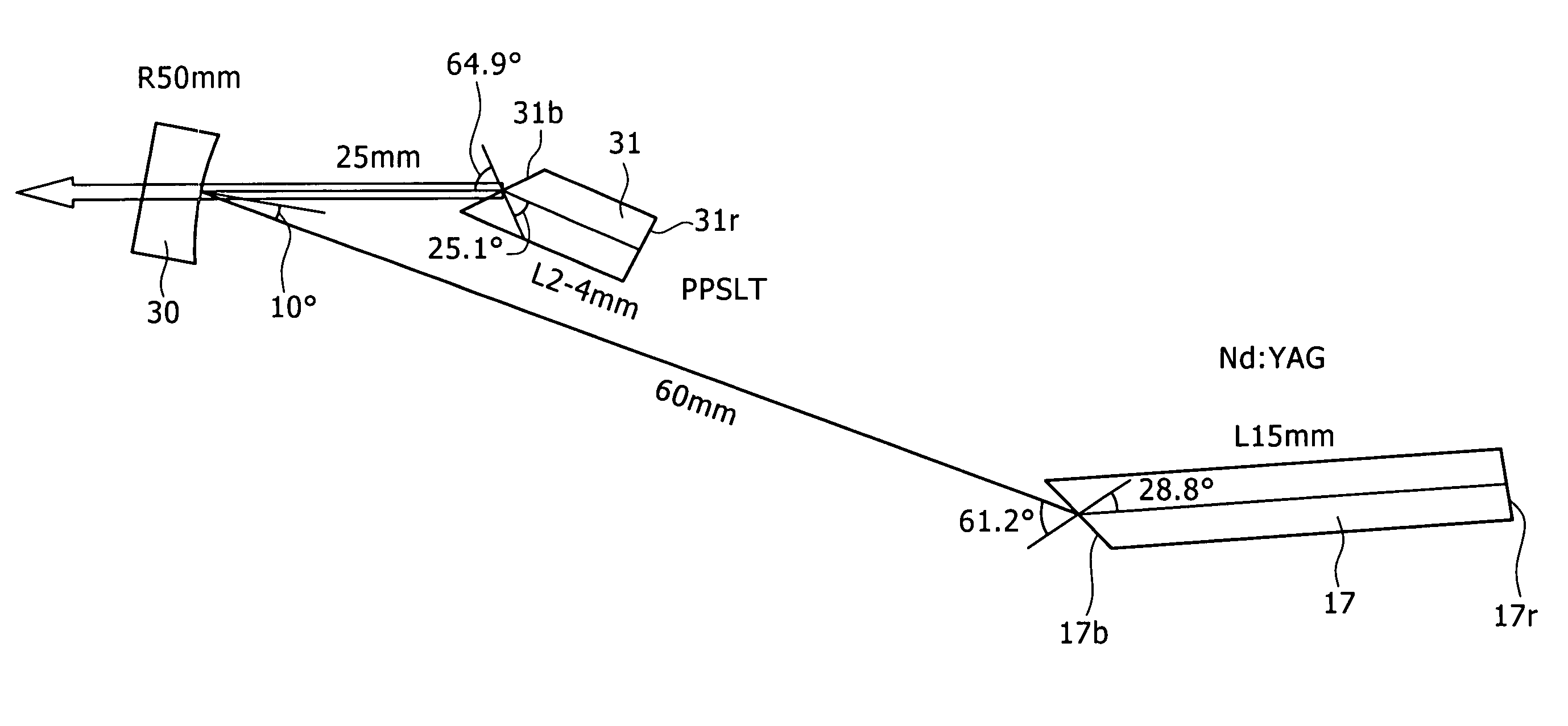
[0053]A laser light source constituting the one-dimensional illumination apparatus 1 is a one-dimensional transverse multiple mode laser, and includes a pumping light source 2, and a laser medium 4 and a wavelength conversion device 5 which are provided in a resonator 3.

[0054]A laser, a discharge lamp and the like may be used as the pu...


PUM


Abstract

A one-dimensional transverse multiple mode laser is used for a one-dimensional illumination apparatus. A pumping light source, and a laser medium and a wavelength conversion device (nonlinear optical crystal or a nonlinear optical device) which are disposed in a resonator, are provided, and the nonlinear optical crystal or a nonlinear optical device is irradiated with a line beam obtained by exciting the laser medium in an elliptic transverse mode pattern. Then, a one-dimensional light modulation device is irradiated with the wavelength-converted line beam, and scanning with the beam modulated by the modulation device is conducted to produce a two-dimensional image. For example, in a green illumination optical system, in the case where the nonlinear optical device for obtaining visible rays through second harmonic generation from IR rays oscillated by a solid state laser medium has a periodical poling structure, stoichiometric composition periodical poling lithium tantalate having been subjected to vapor transport equilibration is used, whereby reliability is enhanced and a reduction in cost can be achieved through mass production.

Description

[0001]This application claims priority of Japanese Patent Application No. JP2004-127181, filed Apr. 22, 2004; Japanese Patent Application No. JP2004-254425, filed on Sep. 1, 2004 and Japanese Patent Application No. JP2005-088819, filed on Mar. 25, 2005 which are all incorporated herein by reference.BACKGROUND OF THE INVENTION[0002]The present invention relates to a technology for contriving higher output and higher efficiency and enhancing image quality and the like in a one-dimensional illumination apparatus and an imaging apparatus which use a one-dimensional transverse multiple mode laser.[0003]Solid state lasers are used in the cases where a high output is desirable. In the cases of using a semiconductor laser as a pumping light source, there have been known, for example, a form in which a laser array having a plurality of emitters (radiation sources) and an optical device (micro-lens array) are combined (see, for example, Japanese Patent Laid-open No. 2001-185792), and a form i...

Claims


Application Information

Patent Timeline
Patent Type & Authority Patents(United States)
IPC IPC(8): H01S3/10H01S3/00H01S3/081H01S3/109H01S3/16H01S5/40H04N9/31
CPCH01S3/109H04N9/3129H01S3/005H01S3/0615H01S3/0816H01S3/094084H01S3/09415H01S3/1611H01S3/1643H01S5/4012H01S5/4031
Inventor OKA, MICHIO
Owner SONY CORP
Learn More