Wavelength conversion laser device and image display device using the same

a laser device and wavelength conversion technology, applied in the direction of laser details, instruments, light demodulation, etc., can solve the problems of reducing conversion efficiency, unable to realize wider tolerance ranges, and restrictive conditions for adjusting and fundamental waves, so as to improve conversion efficiency, reduce speckle noise, and stabilize high power emission

Active Publication Date: 2011-07-14
PANASONIC CORP
View PDF4 Cites 21 Cited by
  • Summary
  • Abstract
  • Description
  • Claims
  • Application Information

AI Technical Summary

Benefits of technology

[0018]According to the foregoing structure, it is possible to achieve a wavelength conversion laser device which permits improved conversion efficiency and stabilized high power emission while outputting low coherent wavelength-converted beams with reduced speckle noises, and it is therefore suitably applied to image display devices. By superimposing a plurality of wavelength-converted beams emitted from the wavelength conversion laser device by the optics and modulating the wavelength-converted beams superimposed by the optics by the modulation element, a most desirable appropriate image display can be realized.

Problems solved by technology

However, because tolerance ranges for a shift from the phase matching condition are inversely proportional to L, a problem arises in that strict conditions are required for the adjustment and the fundamental waves.
This heat generation makes the temperature of the wavelength converter inhomogeneous, which would result in lower conversion efficiency.
However, they fail to find ways to realize wider tolerance ranges in view of a shift from the phase matching condition while maintaining high conversion efficiency.
Furthermore, when the power of the fundamental laser beam is concentrated to particular positions in the nonlinear optical crystal, the wavelength conversion efficiencies by the nonlinear optical crystal would be lowered due to light-induced damage and heat generation, resulting in unstable operations of the wavelength conversion laser device.
However, they fail to consider heat generation for high power frequency converted laser beams, and therefore such problems as lower conversion efficiencies and complex temperature controls for high power converted laser beams remain unsolved.
The foregoing conventional structures also fail to wind ways to realize higher conversion efficiencies when adopting a multi-mode laser light source for the fundamental laser light source.
Furthermore, conventional wavelength conversion laser devices oscillate only a laser beam having a narrow spectrum width due to strict phase matching conditions, and large interference noises by laser beams raise additional problems in the field of video or the like.

Method used


Image

  • Wavelength conversion laser device and image display device using the same
  • Wavelength conversion laser device and image display device using the same
  • Wavelength conversion laser device and image display device using the same

Examples


fourth embodiment

[0104]FIG. 6A through FIG. 6C are schematic views of wavelength converters 52 and 53 according to a fourth embodiment. Members having the same structures and functions as those of the first through third embodiments above are designated by the same reference numerals.

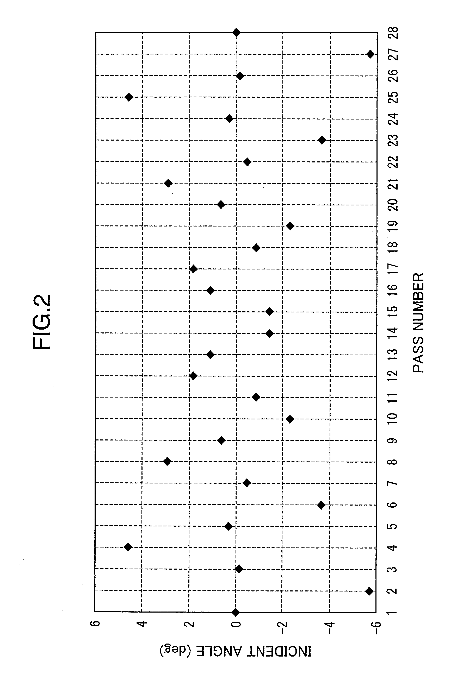
[0105]The wavelength converters 52 and 53 perform wavelength conversion by pseudo phase matching of the poled structure. The wavelength converter 52 includes a portion with periodically poled structure 52a and portions without periodically poled structure 52b in the thickness-wise direction of the frequency converter. The thickness-wise direction of the wavelength converter 52 referred to herein is a direction perpendicular to the sheet surface of FIG. 1 and it is a direction in which a beam path of a laser beam reciprocating between the reflective surfaces hardly shifts. When a laser beam reciprocates between the reflective surfaces, the incident angle of the laser beam into the wavelength converter 52 hardly changes i...

fifth embodiment

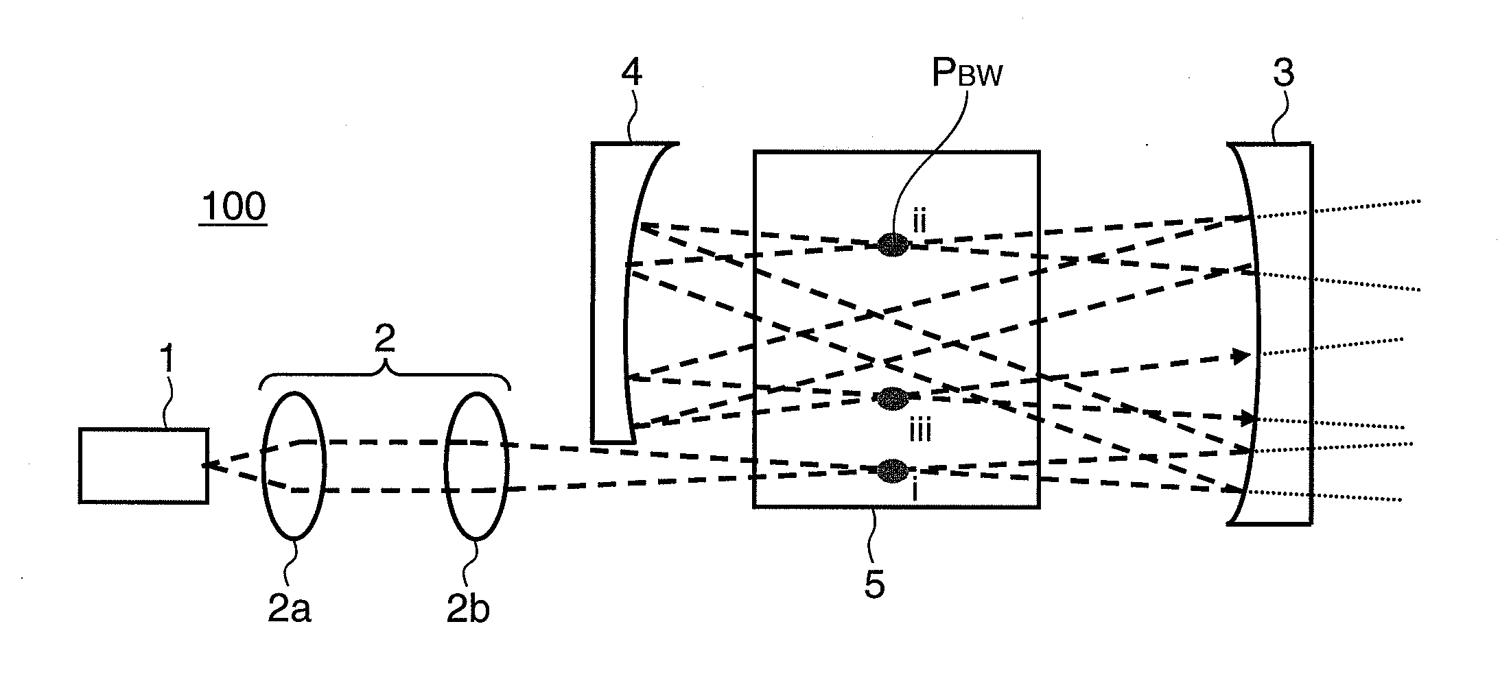
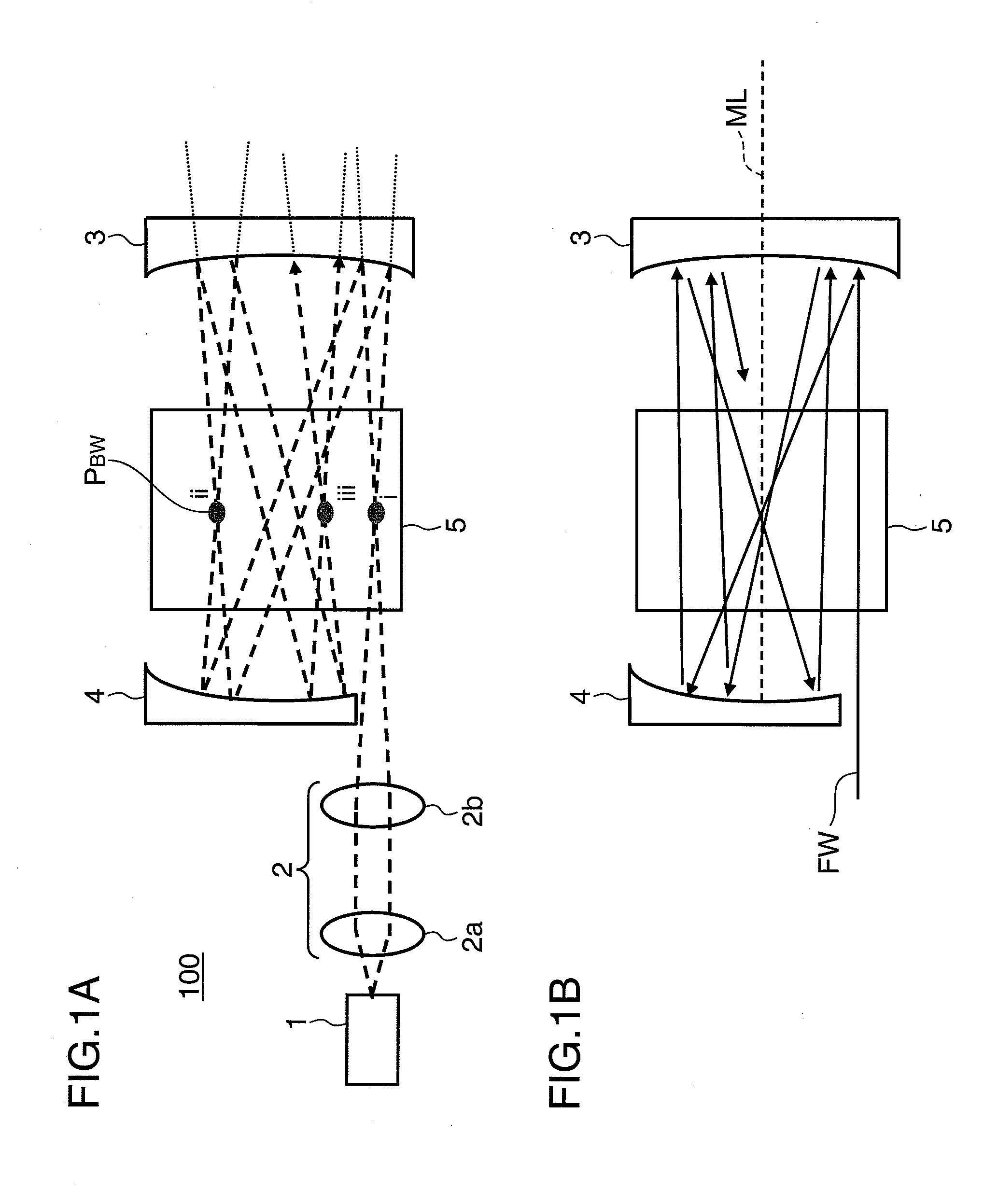
[0110]FIG. 7A and FIG. 7B are schematic views of a wavelength conversion laser device 400 according to a fifth embodiment. FIG. 7A is schematic top view of the wavelength conversion laser device 400 showing the width-wise direction of the wavelength converter 5. FIG. 7B is a schematic side view of the wavelength conversion laser device 400 showing the thickness-wise direction of the wavelength converter 5. Members having the same structures and functions as those of the first through fourth embodiments above are designated by the same reference numerals. The wavelength conversion laser device 400 shown in FIG. 7A and FIG. 7B includes a fundamental laser light source 1, condensing optics 22, a first concave mirror 3, a second concave mirror 4, and a wavelength converter 5.

[0111]The condensing optics 22 that controls and condenses a laser beam to be injected between the reflective surfaces is a preferable embodiment in which the lens power in the thickness-wise direction of the wavele...

sixth embodiment

[0113]FIG. 8A and FIG. 8B are schematic views of a wavelength conversion laser device 500 according to a sixth embodiment. FIG. 8A is a schematic top view of the wavelength conversion laser device 500 indicating the width-wise direction of the wavelength converter 5. FIG. 8B is a schematic side view of the wavelength conversion laser device 500 indicating the thickness-wise direction of the wavelength converter 5. Members having the same structures and functions as those of the first embodiment above are designated by the same reference numerals. The wavelength conversion laser device 500 shown in FIG. 8A and FIG. 8B includes a fundamental laser light source 1, condensing optics 2, an anamorphic reflection mirror 31, a second concave mirror 4, and a wavelength converter 5.

[0114]In the present embodiment, the anamorphic reflection mirror 31 is used instead of the first concave mirror used in the first embodiment above. A coating that reflects a fundamental laser beam and transmits a ...


PUM

PropertyMeasurementUnit
full width at half maximumaaaaaaaaaa
incident anglesaaaaaaaaaa
beam waist radiiaaaaaaaaaa

Abstract

A wavelength conversion laser device includes a laser light source which emits a laser beam, two reflective surfaces which reflect therefrom a laser beam, a wavelength converter provided between the two reflective surfaces, which converts a laser beam into a wavelength-converted laser beam, and condensing optics which condense the laser beams to be injected between the two reflective surfaces, wherein at least one of the two reflective surfaces has a curvature for reflecting a laser beam to be re-injected into the wavelength converter between the two reflective surfaces repeatedly while forming multi paths of laser beams injected into the wavelength converter at different incident angles, and the condensing optics are arranged to disperse beam waists of the laser beams in the wavelength converter, which reciprocate between the two reflective surfaces.

Description

[0001]This application is entitled to the benefit of Provisional Patent Application No. 60 / 960,489, filed in United States Patent and Trademark Office on Oct. 1, 2007.[0002]In addition, this application is based on Japanese patent application serial No. 2008-034133, filed in Japan Patent Office on Feb. 15, 2008, the contents of which are hereby incorporated by reference.TECHNICAL FIELD[0003]The present invention relates to a wavelength conversion laser device which outputs a wavelength-converted laser beam through wavelength conversion of a fundamental laser beam and also relates to an image display device using the same.BACKGROUND ART[0004]There has been a wavelength conversion laser device that performs wavelength conversion using a nonlinear optical phenomenon of a wavelength converter, so that the wavelength of a fundamental wave laser beam is converted to a converted wave laser beam, such as second harmonic generation (SHG), sum frequency generation, and difference frequency ge...

Claims


Application Information

Patent Timeline
Patent Type & Authority Applications(United States)
IPC IPC(8): G02F1/35H01S3/10
CPCG02F1/353H01S3/0092H01S3/005G02F2001/3542G02F1/3542
Inventor MIZUSHIMA, TETSUROFURUYA, HIROYUKIKUSUKAME, KOICHIMIZUUCHI, KIMINORIYAMAMOTO, KAZUHISAHORIKAWA, NOBUYUKISHIKII, SHINICHIITOH, TATSUO
Owner PANASONIC CORP
Why Eureka
Try Eureka