Rotor for Motor and Method for Producing the Same

a technology of bonding magnet and rotor, which is applied in the direction of magnetic circuit rotating parts, magnetic circuit shape/form/construction, magnetic bodies, etc., can solve the problems of general poor thermal stability and bonding force of soft adhesive, damage to the magnet, etc., to achieve high output and efficiency, stable and small pole pitch and dispersion, and high structural reliability

Inactive Publication Date: 2008-09-11
HITACHI METALS LTD
View PDF12 Cites 49 Cited by
  • Summary
  • Abstract
  • Description
  • Claims
  • Application Information

AI Technical Summary

Benefits of technology

[0058]According to the invention, a magnet rotor, in which bonding strength is high between a magnet section and a soft magnetic yoke section and structural reliability is high even in high speed use, can be provided by integral forming of a rotor from bond magnet powder, which contains a binder agent such as resin binder, etc., and soft magnetic powder. Also, the manufacturing process of forming under compression is separated into preforming at low pressure and main forming at high pressure and axes of easy magnetization of magnets are arranged in a necessary, magnetic field in the process of preforming, so that it is possible to obtain a magnetic rotor, which is stable and small in pole pitch and dispersion of magnetic intensity, irrespective of the number of magnetic poles and dimensions of a rotor. Further, not only radial polarization and polar anisotropic polarization but also polarization, in which a single magnetic pole is substantially parallel up to both ends, and further complex polarization, can be controlled, and a magnetic pole pattern, which is difficult to realize in the related art, can be formed on a magnet rotor to contribute to making a motor high in output and efficiency.

Problems solved by technology

Here, when bonding strength is insufficient between respective magnets and respective soft magnetic yokes, which form a rotor, and between the magnets and the soft magnetic yokes, exfoliation and breakage of the magnets are caused.
Since a centrifugal force is increased in substantially proportion to a second power of a rotating speed, such problem becomes serious with high speed rotation.
Also, a soft adhesive is generally poor in thermal stability and bonding force.
In this manner, there are many technical problems in a bonding work of a magnet rotor irrespective of a shape of a magnet.
In such case, however, an effective air gap widens to make magnetic flux from the magnets hard to reach a stator, so that motor output is decreased.
Further, a protective ring made of metal such as stainless steel, etc. generates an eddy current loss to lead to a decrease in motor efficiency.
However, the ring-shaped magnet and a soft magnetic yoke are bonded together by adhesion to be insufficient in bonding strength and reliability.

Method used


Image

  • Rotor for Motor and Method for Producing the Same
  • Rotor for Motor and Method for Producing the Same
  • Rotor for Motor and Method for Producing the Same

Examples


embodiment 1

Comparative Example 1

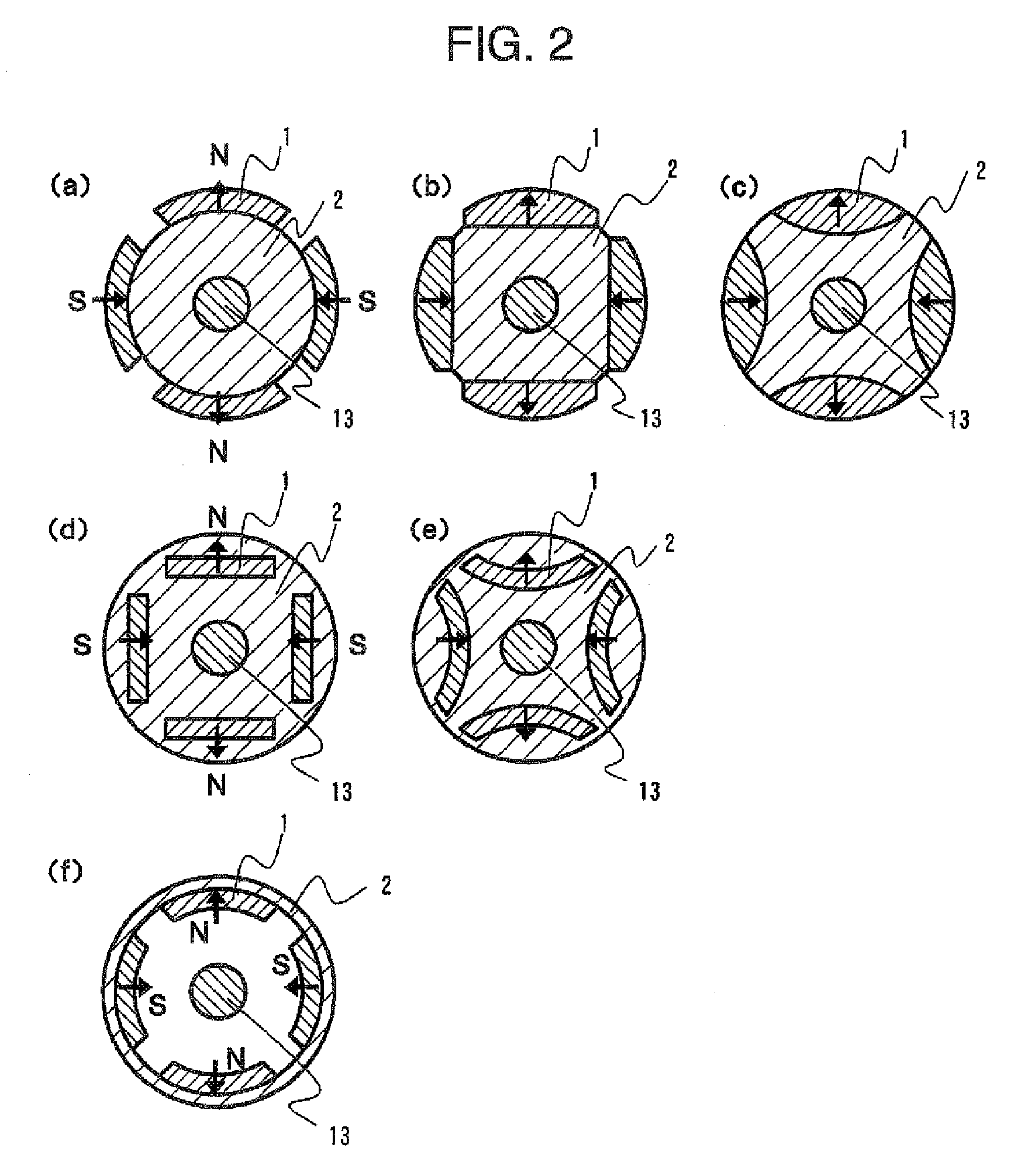
[0060]First, an explanation will be given to an importance in the relative, positional relationship between left and right imaging elements in a stereo camera. First, effects of making the most of that high bonding strength between a bond magnet section and a soft magnetic yoke section, which constitutes a feature of a manufacturing method of the invention, to cancel a protective ring have been examined. A protective ring as shown in FIG. 3 is essential in a conventional system (Comparative example 1), in which segment magnets are bonded. In contrast, when a rotor (FIG. 1(a)) fabricated by the manufacturing method of the invention is used, a rare-earth bond magnet section and a soft magnetic yoke section made of soft magnetic powder can be unified firmly, so that a protective ring is dispensed with and a gap between a stator and a rotor can be made small, thus enabling making further effective use of magnetic flux than in Comparative example 1. Also, a decrease ...

embodiment 2

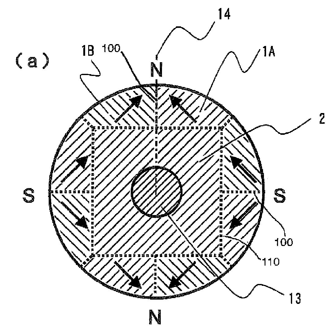
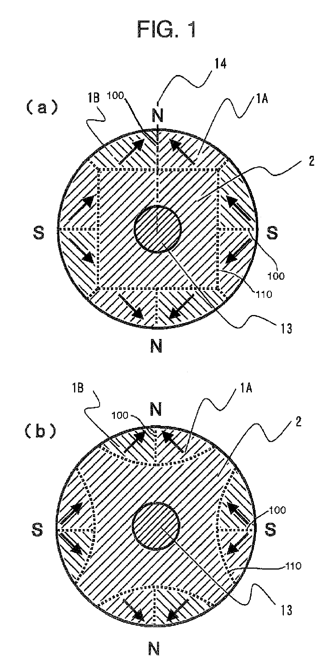
[0065]FIG. 1 is a cross sectional view schematically showing a permanent magnet rotor according to a further embodiment of the invention. In FIG. 1, one magnetic pole is constituted by two magnets 1A, 1B, a yoke 2 made of a soft magnetic material, and a shaft 13. According to the manufacturing method of the invention, it is possible to mount a multiplicity of permanent magnets, which are complex in shape and orientation. As shown in FIG. 1, when anisotropic bond magnets 1A, 1B are oriented so that directions of magnetization of magnets indicated by arrows are made symmetrical with respect to a bonding interface 100 of the anisotropic bond magnets 1A, 1B, generated magnetic fields are efficiently concentrated in a center position of the magnetic poles shown by N(S) in the drawing, and high magnetic properties can be obtained as compared with the case where one magnetic pole is constituted by a single magnet shown in FIG. 2. An extent, to which generated magnetic fields are concentrat...

embodiment 3

[0067]FIG. 10 is a cross sectional view schematically showing a permanent magnet rotor according to a further embodiment of the invention. With a conventional ring magnet manufacturing method, although a magnet has a large thickness in a direction of magnetization as shown in FIG. 10(a), orientation and orientation of multiple poles are difficult, but stable orientation and polarization can be readily performed irrespective of the number of poles and dimensions of a magnet in the manufacturing method of the invention. Also, as shown in FIGS. 10(b) and 10(c), it is also possible to compose one pole of three magnets 1A to 1C to efficiently concentrate generated magnetic fields in a center position of magnetic poles.


PUM

PropertyMeasurementUnit
angleaaaaaaaaaa
shear strengthaaaaaaaaaa
angleaaaaaaaaaa

Abstract

A surface magnet type rotor and an inner magnet type rotor having good motor characteristics in which bonding strength is high between a magnet section and a soft magnetic yoke section, and structural reliability is high even in high speed use, and its producing method. The rotor comprises an anisotropic bond magnet section and a soft magnetic section wherein the anisotropic bond magnet section is preformed in magnetic field and then formed to be integrated with the soft magnetic section in nonmagnetic field. Subsequently, it is heat hardened to produce a surface magnet type rotor. Magnet units, each having a magnetic pole composed by bonding a pair of permanent magnets such that the directions of magnetization become symmetric with respect to the bonding surface, are linked such that magnetic poles of different polarities appear alternately on the magnetic action surface thus forming an anisotropic magnet body. Good motor characteristics can be attained by setting an angle to 5-40° between the direction of magnetization of the permanent magnet and a diametral direction passing the bonding surface.

Description

TECHNICAL FIELD[0001]The present invention relates to a bond magnet rotor for motors, which is integrated with a soft magnetic yoke and provided for the purpose of making motors, generators and so on with use of permanent magnets to have a high efficiency.BACKGROUND ART[0002]Conventionally, various structures of a bond magnet rotor of motors have been proposed, which are generally classified into two systems. A first system comprises a so-called surface permanent magnet (referred below to as SPM) rotor, in which permanent magnets are arranged on magnetic pole surfaces as shown in FIGS. 2(a) to 2(c) and 2(f). In contrast, a second system comprises an interior permanent magnet (referred below to as IPM) rotor, in which permanent magnets are arranged in a rotor as shown in FIGS. 2(d) and 2(e). The former SPM rotor is of a type, in which permanent magnets arranged on a rotor surface are opposed to a stator with an air gap therebetween, and which has characteristics in being easy in desi...

Claims


Application Information

Patent Timeline
Patent Type & Authority Applications(United States)
IPC IPC(8): H02K1/27H01F41/02H02K1/02B22F3/02B22F1/00H02K15/03
CPCH01F1/0578H01F1/22H01F41/028H02K15/03H02K1/2733H02K1/278H02K1/246H02K1/27H02K1/02
Inventor MASUZAWA, MASAHIROMITA, MASAHIROKIKUTI, KEIKO
Owner HITACHI METALS LTD
Why Eureka
Try Eureka