Laser driving circuit, laser driving method, projector apparatus and apparatus which uses laser light

A technology of laser drive and circuit, which is applied in the direction of using projection device image reproducer, circuit, laser, etc., to achieve the effect of reducing speckle noise

Inactive Publication Date: 2013-10-23
SONY CORP
View PDF7 Cites 21 Cited by
  • Summary
  • Abstract
  • Description
  • Claims
  • Application Information

AI Technical Summary

Problems solved by technology

This speckle noise is a problem caused not only by laser display devices but also by general devices using laser light which is coherent light.

Method used


Image

  • Laser driving circuit, laser driving method, projector apparatus and apparatus which uses laser light
  • Laser driving circuit, laser driving method, projector apparatus and apparatus which uses laser light
  • Laser driving circuit, laser driving method, projector apparatus and apparatus which uses laser light

Examples


no. 1 example

[0047] 2-1 Basic configuration of laser drive circuit

[0048] 2-2 Working example 1

[0049] 2-3 Variation of working example 1

[0050] 2-4 Working Example 2

[0051] 2-5 working example 3

[0052] 2-6 Working Example 4

[0053] 2-7 Application examples

[0054] 3. The second embodiment

[0055] 3-1 Working example 1

[0056] 3-2 Application example

[0057] 4. The configuration of this disclosure

[0058]

[0059] The laser drive circuit of the present disclosure is used to drive a plurality of laser sources emitting laser light (ie, laser beams) of different wavelengths. As the laser light source, for example, three RGB laser light sources emitting laser beams of three different wavelengths of red (R), green (G), and blue (B) may be used. For the laser light source, it is preferable to use a semiconductor laser that is smaller in size and higher in efficiency than other light sources. However, a semiconductor laser is an example, and the laser source is not limi...

no. 2 example

[0074] As a device of the present disclosure using laser light, a projector device (in particular, a laser beam scanning type projector device) is exemplified. The system configuration of the projector device according to the first embodiment is described below.

[0075] System Configuration of Projector Device According to First Embodiment

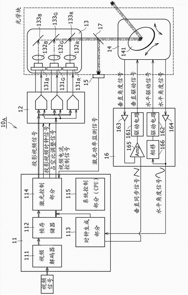
[0076] figure 1 is a system block diagram showing an example of the configuration of the laser beam scanning type projector device according to the first embodiment. Configuring the projector device 10 according to the present embodiment A , so that it includes a video signal processing circuit 11 , a laser drive circuit 12 , a clock generation section 13 , a scanner section 14 , a light receiving element 15 , and a scanner drive circuit 16 .

[0077] The video signal processing circuit 11 includes a video decoder 111 , a frame memory 112 , a clock generation section 113 , a laser control section 114 , and a system control section 115 ...

example 1

[0131] Figure 12 shows a duty cycle adjustment circuit 125 with a circuit example 1 A An example of the configuration of the superimposed signal oscillator 123. refer to Figure 12 , the superposition signal oscillator 123 has the configuration of a ring oscillator including inverters 123 connected in a ring 1 , another inverter 123 2 and yet another inverter 123 3 .

[0132] In this ring oscillator, the inverter 123 of the third stage 3 Output a basic waveform of oscillation with phase = 6 / 6T, where T is the period. The waveform of phase=5 / 6T is obtained from the inverter 123 of the second stage 2 output. Phase = 4 / 6T waveform from the inverter 123 of the first stage 1 output.

[0133] Duty cycle adjustment circuit 125 A Includes phase selector 123 4 , "OR" gate 123 5 and a duty ratio inverting circuit 123 6 . The duty cycle adjustment circuit 125 A , the phase selector 123 4 Receives an inverted waveform of phase = 5 / 6T, a waveform of another phase = 4 / 6T, ...


PUM


Abstract

The invention discloses a laser driving circuit, a laser driving method, a projector apparatus and an apparatus which uses laser light. The laser driving circuit includes a plurality of laser driving video current generation circuits configured to generate a plurality of kinds of laser driving current for driving a plurality of laser light sources configured to emit laser light having wavelengths different from each other based on an inputted video signal; a high frequency superposition section configured to superpose a high frequency signal having a frequency higher than a frequency band of the video signal on the laser driving current generated by the laser driving video current generation circuits; and a waveform correction section configured to correct a waveform of the high frequency signal.

Description

technical field [0001] The present disclosure relates to a laser driving circuit, a laser driving method, a projector device, and a device using a laser (ie, a laser beam). Background technique [0002] As a device using laser light (ie, laser beam), for example, a laser display device that displays an image using laser light is available. In the laser display device, a laser source for emitting laser light is driven by a laser drive circuit, and a scanner scans the laser light to display images on a screen under the drive of the laser drive circuit. A laser display device of the type described in this way is disclosed, for example, in Japanese Patent Laid-Open No. 2010-66303. Contents of the invention [0003] In the laser display device, the optical path length of the laser light after the laser light is emitted from the laser source until it passes through the screen to the viewer's eyes to form an image varies randomly by minute irregularities of the screen. Then, in...

Claims


Application Information

Patent Timeline
Patent Type & Authority Applications(China)
IPC IPC(8): H01S5/042H04N5/74H04N9/31
CPCH04N5/74H04N9/3155H04N9/3129G03B21/2033G03B21/206H01S5/042H01S5/0427H01S5/06213H01S5/4093H01S2301/02H04N9/3161H01S5/0261
Inventor 栗原努木村基
Owner SONY CORP
Why Eureka
Try Eureka