Laser drive circuit and drive method, projector device, and device using laser
A technology of laser drive and circuit, which is applied in the direction of using projection device image reproducer, circuit, laser, etc., to achieve the effect of reducing speckle noise
- Summary
- Abstract
- Description
- Claims
- Application Information
AI Technical Summary
Problems solved by technology
Method used
Image
Examples
no. 1 example
[0047] 2-1 Basic configuration of laser drive circuit
[0048] 2-2 Working example 1
[0049] 2-3 Variation of working example 1
[0050] 2-4 Working Example 2
[0051] 2-5 working example 3
[0052] 2-6 Working Example 4
[0053] 2-7 Application examples
[0054] 3. The second embodiment
[0055] 3-1 Working example 1
[0056] 3-2 Application example
[0057] 4. The configuration of this disclosure
[0058]
[0059] The laser drive circuit of the present disclosure is used to drive a plurality of laser sources emitting laser light (ie, laser beams) of different wavelengths. As the laser light source, for example, three RGB laser light sources emitting laser beams of three different wavelengths of red (R), green (G), and blue (B) may be used. For the laser light source, it is preferable to use a semiconductor laser that is smaller in size and higher in efficiency than other light sources. However, a semiconductor laser is an example, and the laser source is not limi...
no. 2 example
[0074] As a device of the present disclosure using laser light, a projector device (in particular, a laser beam scanning type projector device) is exemplified. The system configuration of the projector device according to the first embodiment is described below.
[0075] System Configuration of Projector Device According to First Embodiment
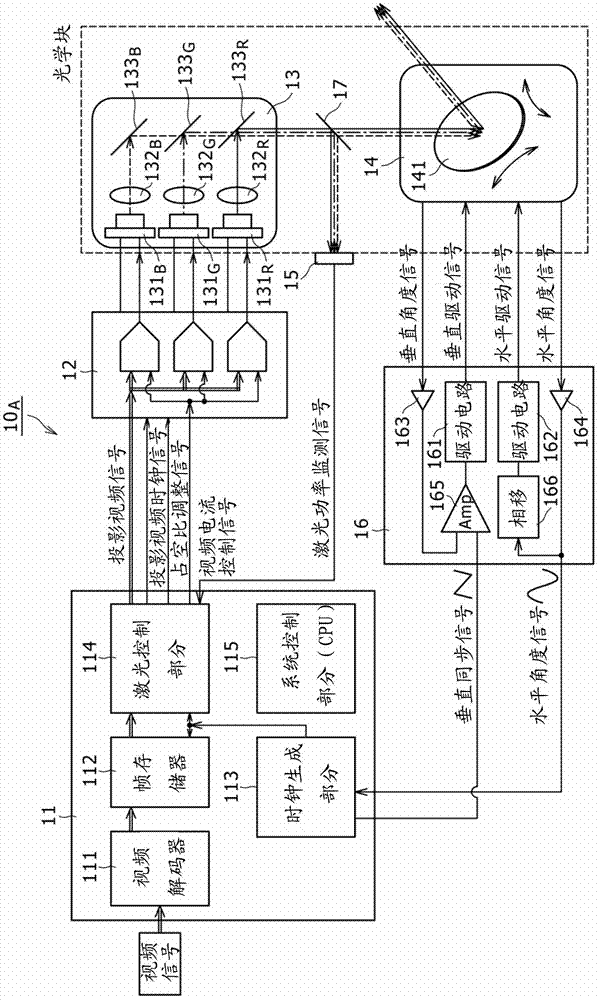
[0076] figure 1 is a system block diagram showing an example of the configuration of the laser beam scanning type projector device according to the first embodiment. Configuring the projector device 10 according to the present embodiment A , so that it includes a video signal processing circuit 11 , a laser drive circuit 12 , a clock generation section 13 , a scanner section 14 , a light receiving element 15 , and a scanner drive circuit 16 .
[0077] The video signal processing circuit 11 includes a video decoder 111 , a frame memory 112 , a clock generation section 113 , a laser control section 114 , and a system control section 115 ...
example 1
[0131] Figure 12 shows a duty cycle adjustment circuit 125 with a circuit example 1 A An example of the configuration of the superimposed signal oscillator 123. refer to Figure 12 , the superposition signal oscillator 123 has the configuration of a ring oscillator including inverters 123 connected in a ring 1 , another inverter 123 2 and yet another inverter 123 3 .
[0132] In this ring oscillator, the inverter 123 of the third stage 3 Output a basic waveform of oscillation with phase = 6 / 6T, where T is the period. The waveform of phase=5 / 6T is obtained from the inverter 123 of the second stage 2 output. Phase = 4 / 6T waveform from the inverter 123 of the first stage 1 output.
[0133] Duty cycle adjustment circuit 125 A Includes phase selector 123 4 , "OR" gate 123 5 and a duty ratio inverting circuit 123 6 . The duty cycle adjustment circuit 125 A , the phase selector 123 4 Receives an inverted waveform of phase = 5 / 6T, a waveform of another phase = 4 / 6T, ...
PUM
 Abstract
Description
Claims
Application Information
 - R&D
- Intellectual Property
- Life Sciences
- Materials
- Tech Scout
- Unparalleled Data Quality
- Higher Quality Content
- 60% Fewer Hallucinations
Browse by: Latest US Patents, China's latest patents, Technical Efficacy Thesaurus, Application Domain, Technology Topic, Popular Technical Reports.
© 2025 PatSnap. All rights reserved.Legal|Privacy policy|Modern Slavery Act Transparency Statement|Sitemap|About US| Contact US: help@patsnap.com


