Image forming apparatus

a technology of forming apparatus and forming chamber, which is applied in the direction of electrographic process apparatus, instruments, optics, etc., can solve the problems of image degradation such as offset, insufficient fixing of toner image, and temperature reduction of toner image, and achieve good coloring

Inactive Publication Date: 2009-06-09
SHARP KK
View PDF8 Cites 6 Cited by
  • Summary
  • Abstract
  • Description
  • Claims
  • Application Information

AI Technical Summary

Benefits of technology

[0011]An object of the invention is to provide an image forming apparatus involving wet fixing that causes no bleeding and coagulation of toner and eventually no disturbance of toner image as a result of application of a fixing fluid, generates no curling or wrinkles in a recording medium, can reduce an amount of power consumption and consumption of the fixing fluid, takes a relatively short time to fix even a multicolored toner image, and can fix toner with large adhesion on a recording medium through which the fixing fluid hardly permeates.

Problems solved by technology

The issue here is that, in the image forming apparatus, a recording medium is not heated, and when a toner image comes into contact with a recording medium at the time of thermal fixing, the toner image is reduced in temperature.
This disadvantageously causes not-fully fixing of the toner image, and image degradation such as offset.
The issue here is that, with the image forming apparatus of JP-A 2004-151626, although the toner image is indeed better fixed to the recording medium, the apparatus requires a larger thermal capacity for a heating section as is heating not only the toner image but also the recording medium.
This resultantly increases the power consumption, and the resulting increased amount of power consumption makes up more than one half of the entire amount.
This resultantly increases the material cost.
Also with thermal fixing, no image fixing is possible until a portion for image fixing reaches a predetermined temperature, thereby taking long to derive the temperature of a predetermined value, i.e., taking long warm-up time.
This causes the resulting fixed image look blurred at the edges, and have inconsistencies at halftone portions that are supposed to show uniformity, thereby being unable to provide the high image quality.
The problem here is that when a fixing fluid remains only at the image sections in a recording medium as such, the image sections expand and contract but not the no-image sections.
There is thus no way of avoiding the image sections and therearound from becoming wrinkled.
Although such an inconvenience is surely prevented if with the minimum amount of fixing fluid needed for swelling of the toner, the minimum amount is extraordinarily small, whereby it is difficult to measure the minimum amount with precision.
When a fixing fluid is applied only to the image sections, background fogging or the like occur because some of the toner attaches the no-image sections around the image sections, and the toner is not fixed and thus remains on the recording medium, thereby sometimes making a user's hands and clothes dirty.
The image forming apparatus of JP-A 10-63121, however, requires a large amount of fixing fluid if wanting to increase the adhesion between the toner image and the recording medium, and the bonding among the toner particles.
The use of large amount of fixing fluid inevitably causes wrinkles and curling to a recording medium.
This results in poor maintainability or size increase of the apparatus.
Considered here is another possible problem if the previous wet-fixing image forming apparatus uses, for fixing of a toner image, a recording medium that is less prone to be permeated with a fixing fluid, e.g., plastic sheet or coated paper including an overhead projector sheet (hereinafter, referred to as “OHP sheet”).
In such a case, the adherence of the toner becomes not sufficient, thereby possibly impairing the completion of the resulting toner image.

Method used


Image

  • Image forming apparatus
  • Image forming apparatus
  • Image forming apparatus

Examples


first embodiment

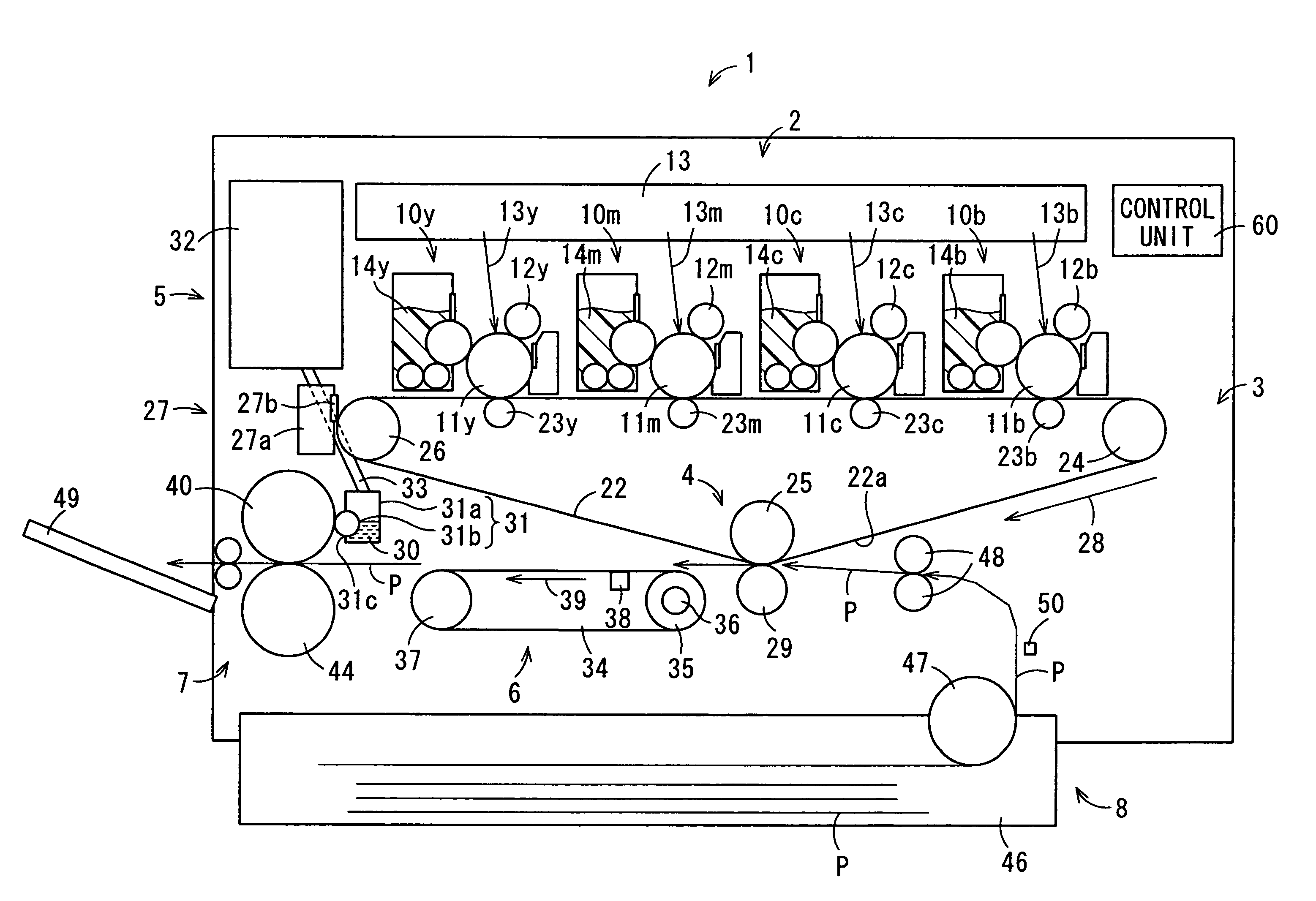
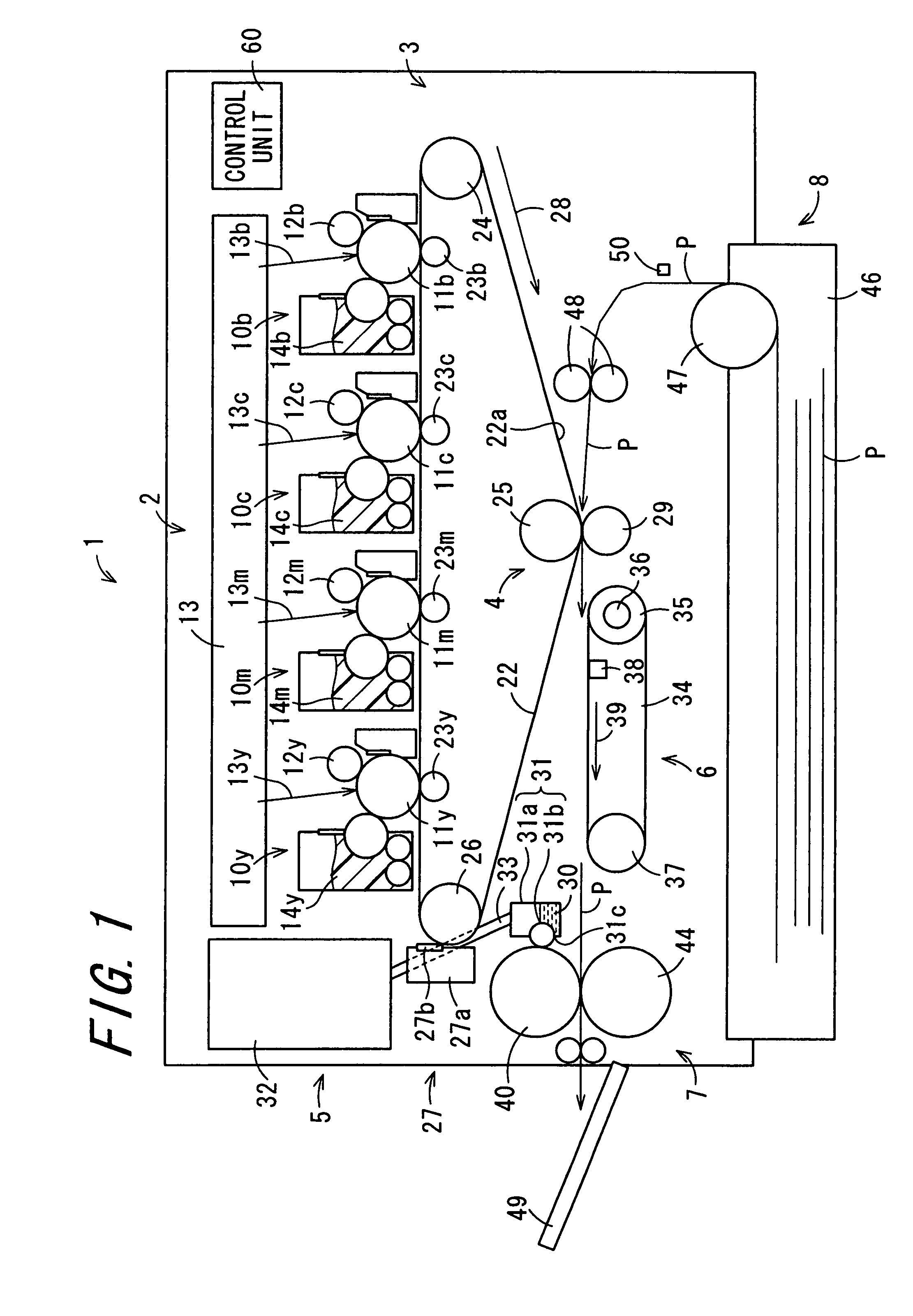
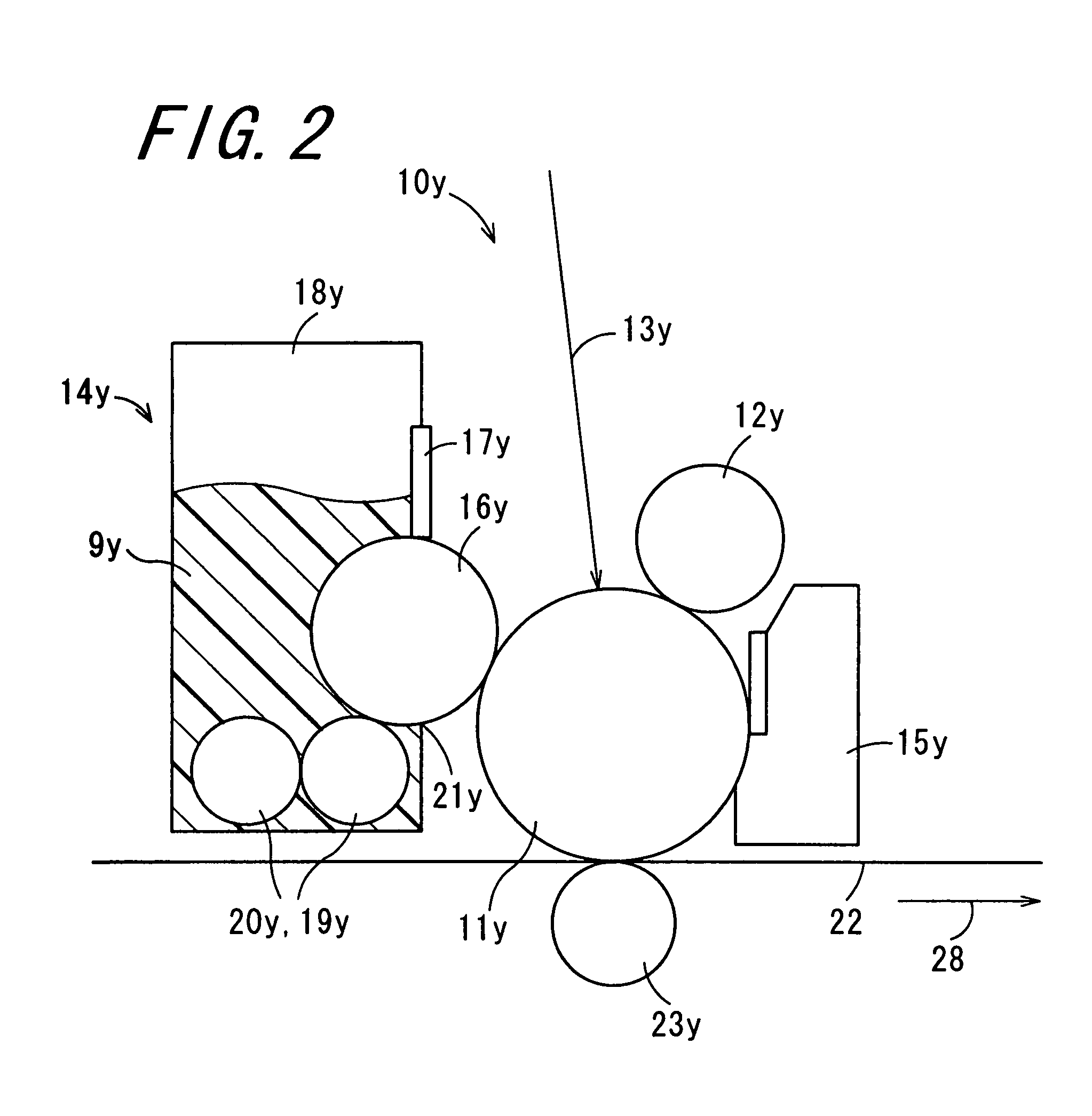
[0048]FIG. 1 is a cross sectional view schematically showing the configuration of an image forming apparatus 1 according to the invention. FIG. 2 is an enlarged cross sectional view of the image forming apparatus of FIG. 1, showing the configuration of a main component therein, i.e., a toner image forming section 2 that will be described later. FIG. 3 is an enlarged cross sectional view of the image forming apparatus of FIG. 1, showing the configurations of main components therein, i.e., a transfer section 4, a part of a fixing fluid applying section 5, a transport section 6, and a fixing section 7, all of which will be described later. FIG. 4 is a cross sectional view schematically showing the configuration of a fixing roller 40 that will be described later. The image forming apparatus 1 is of an electrophotographic type with the tandem configuration. In the image forming apparatus 1, toner images of four colors, i.e., yellow, magenta, cyan, and black, are transferred by sequential...

second embodiment

[0098]FIG. 5 is a cross sectional view schematically showing the configuration of a main component of an image forming apparatus 51 according to the invention. The image forming apparatus 51 is similar to the image forming apparatus 1, and any components similar to those in the image forming apparatus 1 is denoted by the same reference numeral or not shown and not described again. In the image forming apparatus 51, as alternatives to the transport section 6 and the fixing section 7 in the image forming apparatus 1, a transport section 52 and a fixing section 53 are provided, and a fixing fluid temperature keeping section 55 is disposed in the fixing fluid storage tank 32 of the fixing fluid applying section 5.

[0099]In the fixing fluid applying section 5, the fixing fluid temperature keeping section 55 is disposed in the inside of the fixing fluid storage tank 32 for the purpose of keeping constant the temperature of the fixing fluid 30. The fixing fluid temperature keeping section 5...


PUM


Abstract

There is provided an image forming apparatus involving wet fixing that causes no bleeding and coagulation of toner and eventually no disturbance of toner image as a result of application of a fixing fluid, generates no curling or wrinkles in a recording medium, and can fix toner with large adhesion on a recording medium through which the fixing fluid hardly permeates. An image forming apparatus includes a toner image forming section, an intermediate transfer section, a transfer section, a fixing fluid applying section, a transport section, a fixing section, a recording medium feeding section, and a recording medium detection section. In the image forming apparatus, control of application amount of a fixing fluid to a recording medium is performed by the fixing fluid applying section based on the result obtained by the recording medium detection section for the recording medium such as thickness and material.

Description

CROSS-REFERENCE TO RELATED APPLICATION[0001]This application claims priority to Japanese Patent Application No. 2006-122714, which was filed on Apr. 26, 2006, the contents of which, are incorporated herein by reference, in their entirety.BACKGROUND OF THE INVENTION[0002]1. Field of the Invention[0003]The present invention relates to an image forming apparatus.[0004]2. Description of the Related Art[0005]An electrophotographic image forming apparatus is popular for use in a copier, printer, facsimile, and the like. In the electrophotographic image forming apparatus, a toner image is transferred directly to a recording medium, e.g., paper, or indirectly thereto after a transfer to an intermediate transfer medium. For such a toner image transfer, used is a photoreceptor having a photosensitive layer including a photoconductive substance formed on the surface thereof. The surface of the photoreceptor is subjected to electric charge injection so that it is uniformly charged, and then an ...

Claims


Application Information

Patent Timeline
Patent Type & Authority Patents(United States)
IPC IPC(8): G03G15/20
CPCG03G15/2025
Inventor TANAKA, ATSUSHIASAKURA, KENJI
Owner SHARP KK
Why Eureka
Try Eureka