Piezoresistive pressure sensor

Inactive Publication Date: 2009-06-16
HONEYWELL INT INC
View PDF18 Cites 21 Cited by
  • Summary
  • Abstract
  • Description
  • Claims
  • Application Information

AI Technical Summary

Problems solved by technology

The silicon-based sensors and actuators may have lim

Method used


Image

  • Piezoresistive pressure sensor
  • Piezoresistive pressure sensor
  • Piezoresistive pressure sensor

Examples


Embodiment Construction

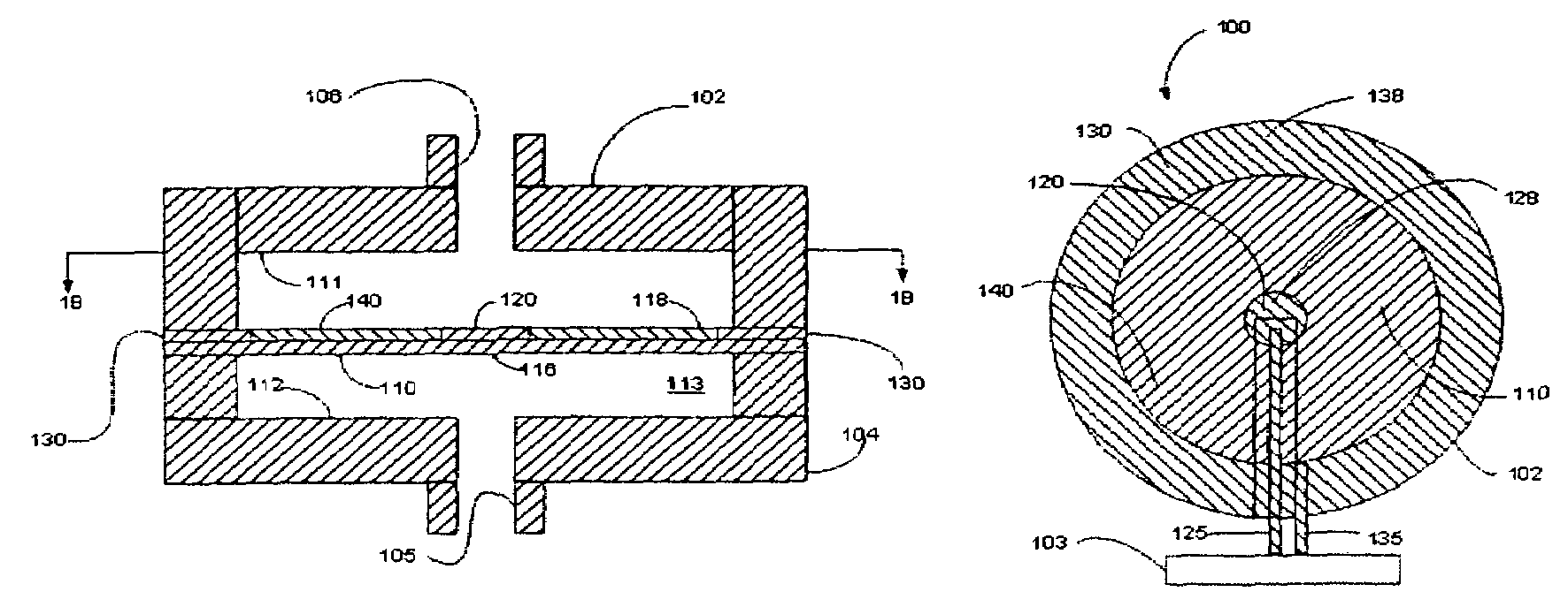
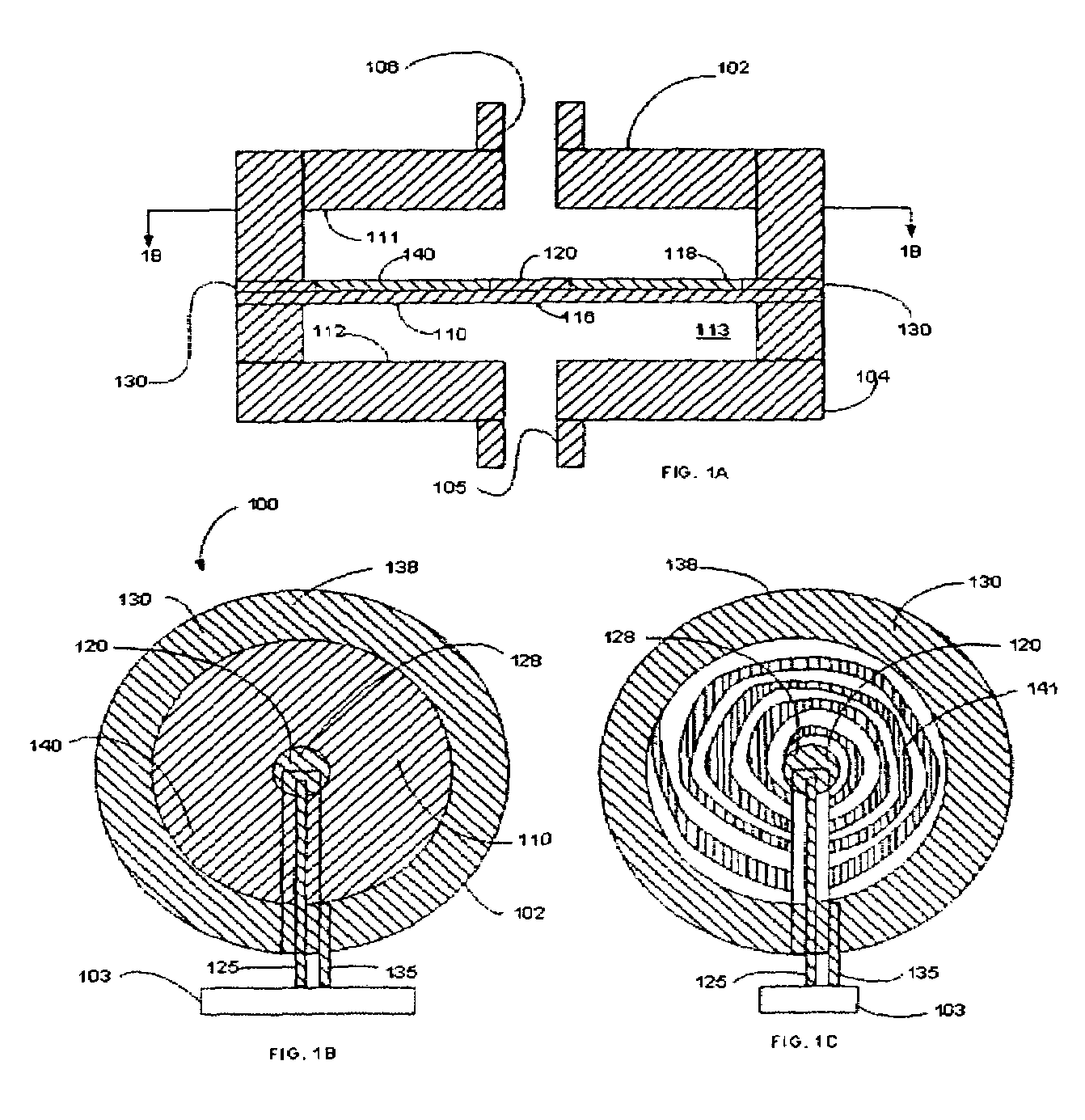
[0016]In embodiments herein, pressure within a fluid chamber of a pressure sensor changes as the pressure of the monitored fluid changes. The polymer diaphragm within the fluid chamber may move, deflect and / or deform as a result of the change in pressure within the fluid chamber. When the diaphragm moves, a variation in resistance of a piezoresistor of the diaphragm may be induced. The electrode outputs coupled to electrodes of the diaphragm may cause a control system to read the change in resistance. The variation in resistance may be proportional to the applied pressure, and therefore, the applied pressure may be measured.

[0017]FIGS. 1A and 1B illustrate a cross-sectional side view and a plan view of a system 100 including a pressure sensor 102 and a control system 103, according to an example embodiment. The pressure sensor 102 includes a housing 104, a fluid inlet 105 of the housing, a vent 106 or fluid outlet port of the housing, and a diaphragm 110 within the housing. The pres...


PUM


Abstract

A pressure sensor includes a housing portion with a fluid inlet and a polymer element within the housing portion. The polymer element may be coated with piezoresistive material to form a first resistor and may have associated electrodes. The polymer element includes a first resistance value that changes to a second resistive value in a response to a predetermined condition. The pressure sensor may also include a second polymer element that includes a first resistance value that changes to a second resistive value in a response to a predetermined condition.

Description

FIELD[0001]This application relates in general to a piezoresistive pressure sensor.BACKGROUND[0002]Some industrial, commercial, medical, aerospace and military systems depend on reliable pressure sensors for fluid (including gas) handling. Pressure transducers that use piezoresistors may be formed with a silicon substrate and an epitaxial layer, which is grown on the substrate. A portion of the substrate is removed, leaving a thin, flexible diaphragm. The piezoresistors are located in the diaphragm to form a pressure transducer.[0003]In operation, at least one surface of the diaphragm is exposed to a process pressure. The diaphragm deflects according to the magnitude of the pressure, and this deflection bends the attached piezoresistors. Bending of the diaphragm may create a change in the resistance value of the piezoresistors. The change in the resistive value may be reflected as a change in the output voltage signal of a resistive bridge formed at least partially by the piezoresis...

Claims


Application Information

Patent Timeline
IPC IPC(8): G01L7/08
CPCG01L9/0055
Inventor CABUZ, EUGEN ICABUZ, CLEOPATRAWANG, TZU-YU
Owner HONEYWELL INT INC
Why Eureka
Try Eureka