Coke oven repairing apparatus

a technology for repairing equipment and coke ovens, which is applied in the direction of lighting and heating equipment, furnaces, separation processes, etc., can solve the problems of large investment, long construction period, and the loss of coke ovens,

Active Publication Date: 2009-06-16
KANSAI COKE & CHEM
View PDF13 Cites 26 Cited by
  • Summary
  • Abstract
  • Description
  • Claims
  • Application Information

AI Technical Summary

Benefits of technology

[0019]According to the present invention, a lance can be inserted through a charging-hole on the top of the oven, and the lance inserted in the carbonizing chamber can be oscillated in the direction of oven length, which widens the repairable range within the carbonizing chamber, thus solving the problem that un-repaired portions are left in the carbonizing chamber.
[0031]With the working device having the aforementioned configuration according to the present invention, it is possible to make repairs over a wider range of the oven walls of the carbonizing chamber of a coke oven without stopping operations.

Problems solved by technology

Such types of coke ovens have gone through over 30 years since they were built and thus become aged.
However, reconstruction of such a huge coke-oven equipment would require enormous investments and long periods of construction works.
This induces the problem that no repairs can be made for the range other than the range 105 that includes the repairable range of the operator 100 and the repairable range of the operator 101.
Although, in theory, the aforementioned repairing device 107 can be placed at both the coke side (coke reception side) and the machine side (coke extrusion side) to enable making repairs all over the inside of the oven, it is not practical to introduce plural large-sized and expensive repairing device 107.
However, the aforementioned repairing device 120 which descends the lance 127 is configured to descend the lance 127 through charging-holes with a diameter of about 40 to 50 cm, thus having the problem that the repairable range is limited to only near the descending path for the lance 127.

Method used


Image

  • Coke oven repairing apparatus
  • Coke oven repairing apparatus
  • Coke oven repairing apparatus

Examples


Embodiment Construction

[0047]Hereinafter, the present invention will be described in detail on the basis of embodiments illustrated in the drawings.

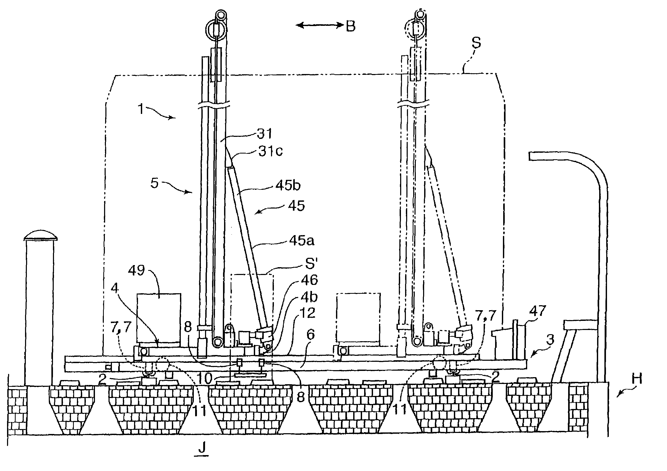
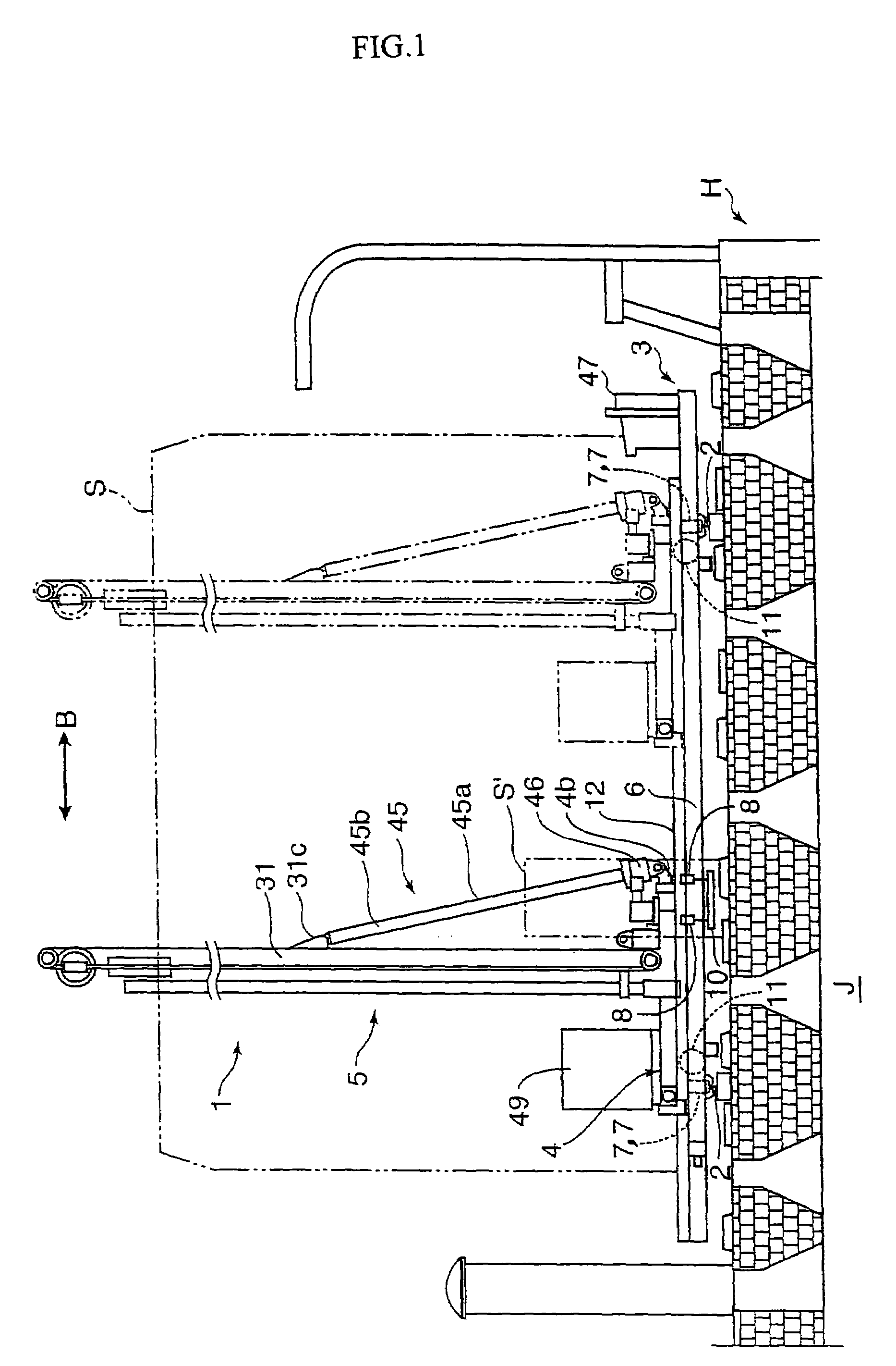
[0048]FIG. 1 illustrates a repairing apparatus according to the present invention which is placed on the top of a coke oven H. A coal-charging car for charging coal into a carbonizing chamber J is placed on the oven, and, in the figure, a two-dot chain line S represents the contour thereof. Further, S′ is a path penetrating through the coal-charging car S in the direction of coke oven battery.

[0049]In the figure, the repairing apparatus 1 is mainly constituted by a traveling carriage 3 which straddles the rails 2, 2 placed on the oven along the direction of coke oven battery to travel on the rails, a traversing carriage 4 which is provided on the traveling carriage 3 and traverses in the direction of oven length (the direction of an arrow B), and a working device 5 mounted on the traversing carriage 4.

[0050]The traveling carriage 3 has a underframe 6 that incl...


PUM


Abstract

A coke-oven repairing apparatus comprising: a traveling carriage 3 which travels in the direction of coke oven battery with the carriage straddled on the rails placed on the top of a coke oven; a traversing carriage 4 provided on said traveling carriage 3, which moves in the direction orthogonal to the direction of coke oven battery; and a working device 5 for making repairs on the oven walls within the coke oven which is mounted on said traversing carriage 4, wherein the working device 5 includes: a guide post 31 which stands on the traversing carriage 4, and is also coupled, at its lower end portion, to a supporting portion provided on the traversing carriage through a pivot shaft 42; a lance 32 which ascends or descends along the guide post 31; and a derricking device 45 which tilts the guide post 31 between a forward-tilted posture and a backward-tilted posture using the pivot shaft 42 as the fulcrum to oscillate the lance 32 inserted in a coke-oven carbonizing chamber through a charging-hole, within the carbonizing chamber.

Description

TECHNICAL FIELD[0001]The present invention relates to a coke-oven repairing apparatus suitable for making repairs on the inner walls of a coke oven.BACKGROUND ART[0002]A coke oven is configured to include carbonizing chambers and combustion chambers made of refractory bricks, wherein the carbonizing chambers and the combustion chambers are alternately placed in the direction of coke oven battery so that heat in the combustion chambers are transferred to the carbonizing chambers through the refractory bricks to cause dry distillation of charged coal within the carbonizing chambers to generate coke. Further, the charging of coal into the carbonizing chambers is performed through a coal-charging car which travels on the top of the coke oven in the direction of coke oven battery.[0003]Such types of coke ovens have gone through over 30 years since they were built and thus become aged. However, reconstruction of such a huge coke-oven equipment would require enormous investments and long p...

Claims


Application Information

Patent Timeline
Patent Type & Authority Patents(United States)
IPC IPC(8): B01D3/00
CPCC10B29/06F27D1/16F27D21/02
Inventor INAMASU HIRONOBUTAKAYAMA NOBUKIHORINOUCHI SHUNJIYAMASHITA HIROFUMI
Owner KANSAI COKE & CHEM
Why Eureka
Try Eureka