Frame rate conversion device, image display apparatus, and method of converting frame rate

a frame rate conversion and image display technology, applied in the field of frame rate conversion devices, image display apparatuses, and conversion methods, can solve the problems of further difficulty in achieving smooth movement of moving images after the frame rate conversion, and achieve the effect of prolonging the definition imag

Active Publication Date: 2009-06-16
MAXELL HLDG LTD
View PDF22 Cites 20 Cited by
  • Summary
  • Abstract
  • Description
  • Claims
  • Application Information

AI Technical Summary

Benefits of technology

[0007]In view of such a problem described above, it is an object of the invention to provide a technology relating to frame rate conversion which makes the movement of image smoother and enables display of extended definition image.
[0010]As described above, according to the invention, the movement of the image after converting the frame rate is smoothened, and hence an extended definition image can be obtained.

Problems solved by technology

Therefore, in the related art, it is difficult to achieve smooth movement of the moving image after the frame rate conversion.
Also, since the time period in which the same frame is displayed is increased, achievement of smooth movement is further difficult.

Method used


Image

  • Frame rate conversion device, image display apparatus, and method of converting frame rate
  • Frame rate conversion device, image display apparatus, and method of converting frame rate
  • Frame rate conversion device, image display apparatus, and method of converting frame rate

Examples


first embodiment

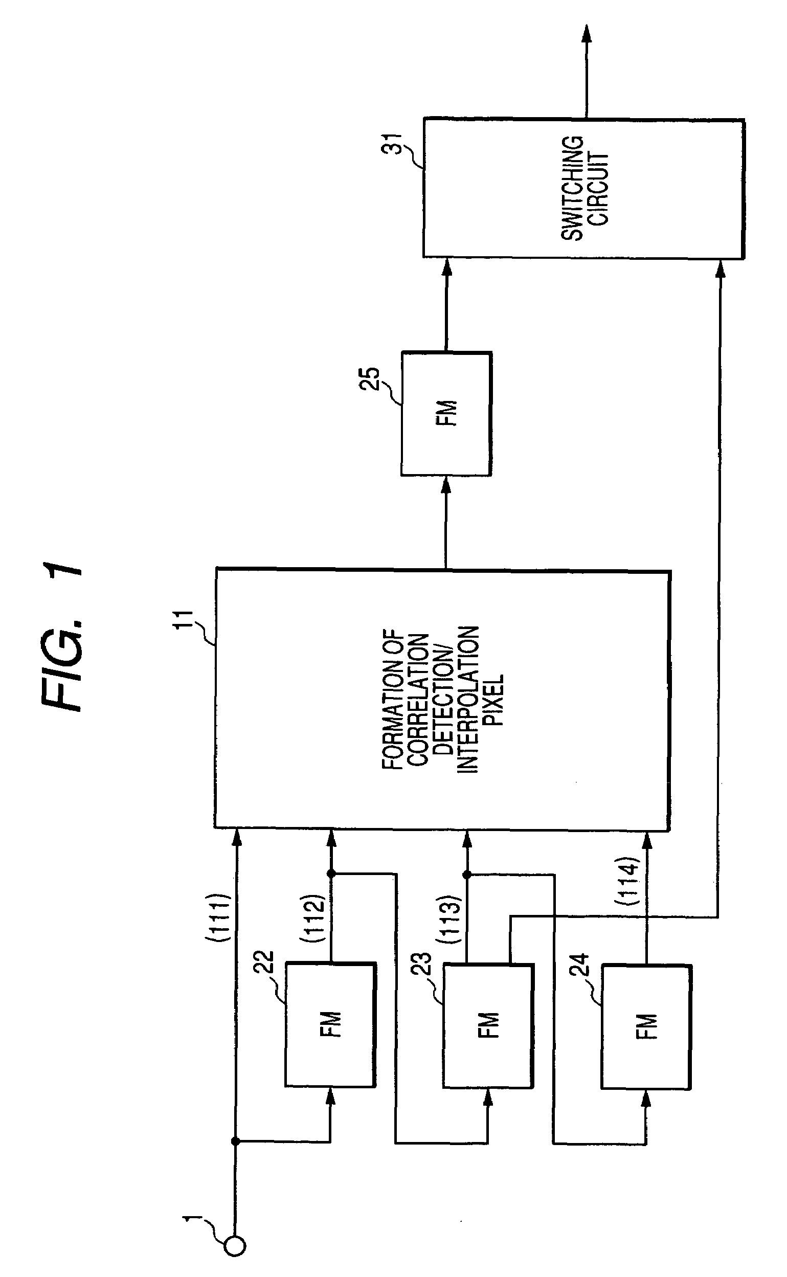
[0018]Referring now to FIG. 1 and FIG. 2, the first embodiment of the invention will be described. FIG. 1 is a block diagram showing the first embodiment of a frame rate conversion unit used in an image display apparatus. In the first embodiment, a case in which an image signal of sequential scanning system of 60 frames per second is inputted, and the frame rate of this image signal is converted into the image signal of double frames, that is, of 120 frames per second will be described as an example. As a matter of course, the frame frequency of the aforementioned inputted image signal may be other frequencies. Needless to say that this embodiment can be applied to the case in which the frame rate is converted in a multiplying factor different from twice (for example, the frequency of 1.5 times or three times) in the same manner. In the following description, it is assumed that the inputted image signal has a digital format. Therefore, when the image display apparatus received an an...

second embodiment

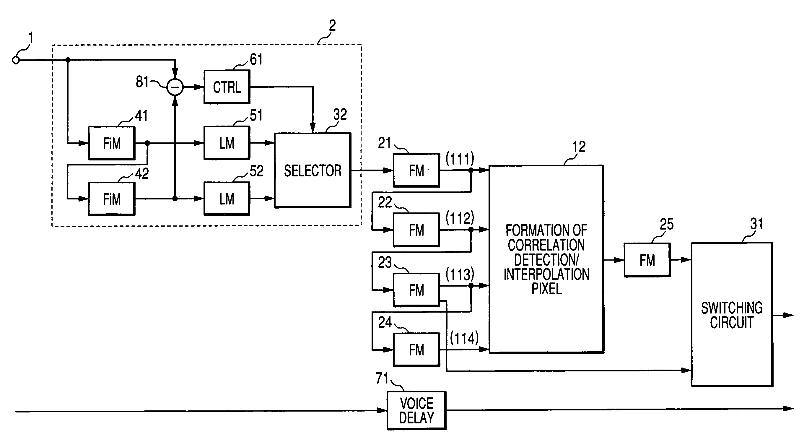
[0048]Referring now to FIG. 3 to FIG. 6, a second embodiment of the invention will be described. This embodiment is described about the case in which the 2-3 pulldowned interlace signal of 60 fields per second (hereinafter referred simply as “2-3 signal”) is inputted, and this signal is converted into a moving image of 60 frames per second as an example.

[0049]FIG. 3 is a circuit block diagram showing the second embodiment of the invention. A point significantly different from the first embodiment shown in FIG. 1 is that a sequential scanning conversion unit 2 is added. This sequential scanning conversion unit includes field memories 41 and 42, a subtracter 81, a controller 61, line memories 51 and 52, and a selector 32. The image signal (2-3 signals) inputted from the signal input terminal 1 is supplied to the field memory 41 and the subtracter 81. The field memory 41 retains and delays the inputted image signal by one field and outputs the same to the field memory 42 and the line m...


PUM


Abstract

The present invention provides a technique relating to a frame rate conversion which enables display of an image of extended definition by smoothening the movement of the image. Therefore, the invention fixes the direction of interpolation using information on a first frame which appeared before the insertion time of the interpolated frame, a second frame appeared before the first frame, a third frame appeared after the insertion time, and a fourth frame appeared after the third frame, based on the insertion time of the interpolated frame. The interpolated pixel is generated from pixels of the second frame and the third frame located in the direction of interpolation, and generates the interpolated frame. Then, the interpolated frame is inserted into the inputted image signal to convert the frame rate.

Description

BACKGROUND OF THE INVENTION[0001]1. Field of the Invention[0002]The present invention relates to a frame rate converting technique for converting the number of image frames used, for example, for an image display apparatus.[0003]2. Description of the Related Art[0004]In the image display apparatus, as a technique for displaying a moving image after having converted a frame rate (frame frequency) of image signal transmitted through a television broadcast into a desired frame rate, for example, a technique described in JP-A-2001-111968 is known.[0005]In the related art described above, when increasing the frame rate of the image signal as a conversion process, a process to repeat the same frame a plurality of times is performed. For example, when doubling the frame rate of an image signal having a frame row of (F1, F2 . . . ), a process to repeat each frame two times each, such as (F1, F1, F2, F2 . . . ) is performed. Therefore, in the image signal after conversion, the position of an...

Claims


Application Information

Patent Timeline
Patent Type & Authority Patents(United States)
IPC IPC(8): H04N7/01
CPCG09G5/00H04N7/0112H04N7/014G09G2340/0435G09G2340/16H04N7/0127
Inventor MIZUHASHI, YOSHIAKINAKAJIMA, MITSUO
Owner MAXELL HLDG LTD
Why Eureka
Try Eureka