Vehicle passenger restraining system

a passenger and bolster technology, applied in the direction of vehicular safety arrangements, vehicle components, pedestrian/occupant safety arrangements, etc., can solve the problems of reducing the contact between the amount of knee bolster contact is difficult to minimize, and the knee bolster cannot provide a sufficient restraining force with respect to the knees of passengers, so as to increase the rearward movement increase the retraining effect of the knee bolster

Inactive Publication Date: 2009-06-30
NISSAN MOTOR CO LTD
View PDF20 Cites 7 Cited by
  • Summary
  • Abstract
  • Description
  • Claims
  • Application Information

AI Technical Summary

Benefits of technology

[0013]In view of the issues just described, one object of the present invention is to provide a vehicle passenger restraining system that is configured and arranged to advance the timing at which the passenger's knees are restrained during a collision by increasing the amount of rearward movement of the knee bolster to reliably restrain the passenger's knees regardless of the positioning of the passenger's lower limbs.
[0014]Also, another object of the present invention is to provide a vehicle passenger restraining system that can advance the timing at which the passenger's knees are restrained in a collision by increasing the amount of rearward movement of the knee bolster and can increase the retraining effect of the knee bolster with respect to the passenger's knees by synchronizing the timing of the rearward movement of the knee bolster and the timing of the restraining action of the seat belt member.

Problems solved by technology

In short, with the conventional vehicle passenger restraining system disclosed in this reference, it is difficult to minimize an impact of a collision to the passenger because the knee bolster does not easily restrain the passenger's knees at a point in time when the amount of forward movement of the passenger is small immediately after the collision occurs.
In such cases, the knee bolster cannot provide a sufficient restraining force with respect to the passenger's knees.
Also, if the timing at which the knee bolster is moved rearward is offset from the timing at which a seat belt retractor executes an emergency wind-in (retraction) of the seat belt member, there is a possibility that the amount of contact between the knees of the passenger and the knee bolster will be diminished when the knee bolster is moved rearward due to a collision.
In such cases, the knee bolster cannot provide a sufficient restraining force with respect to the passenger's knees.

Method used


Image

  • Vehicle passenger restraining system
  • Vehicle passenger restraining system
  • Vehicle passenger restraining system

Examples


second embodiment

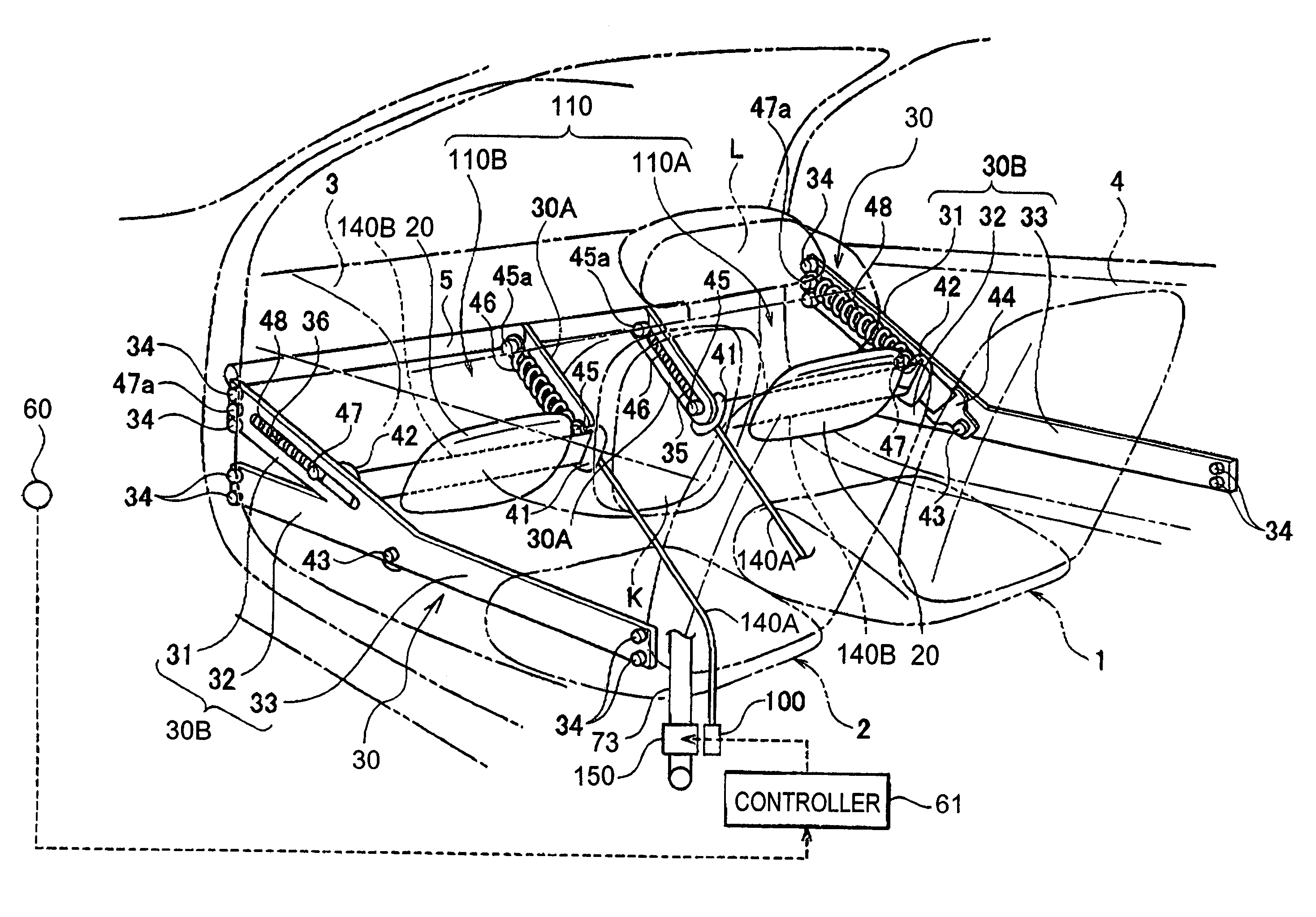
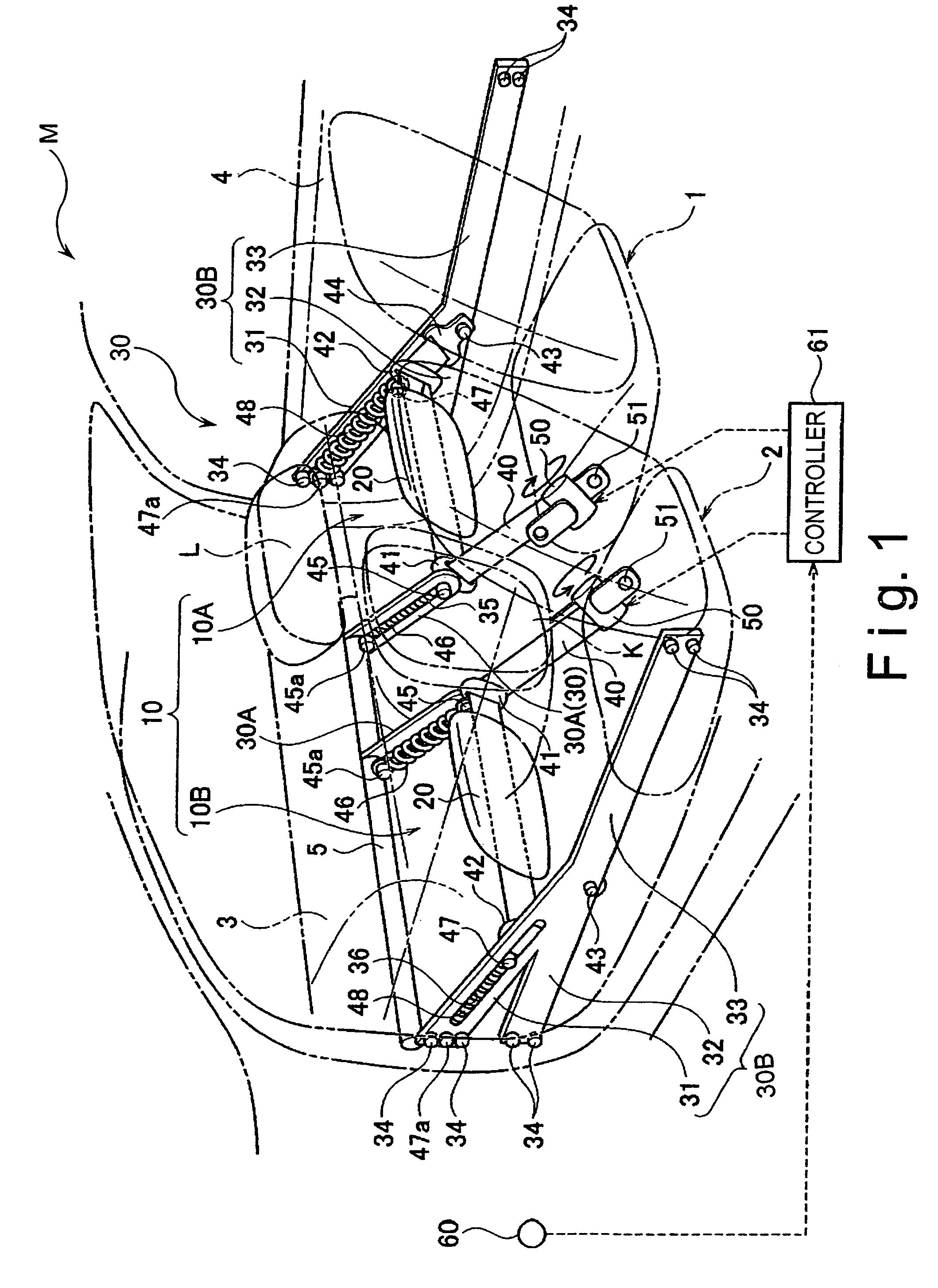
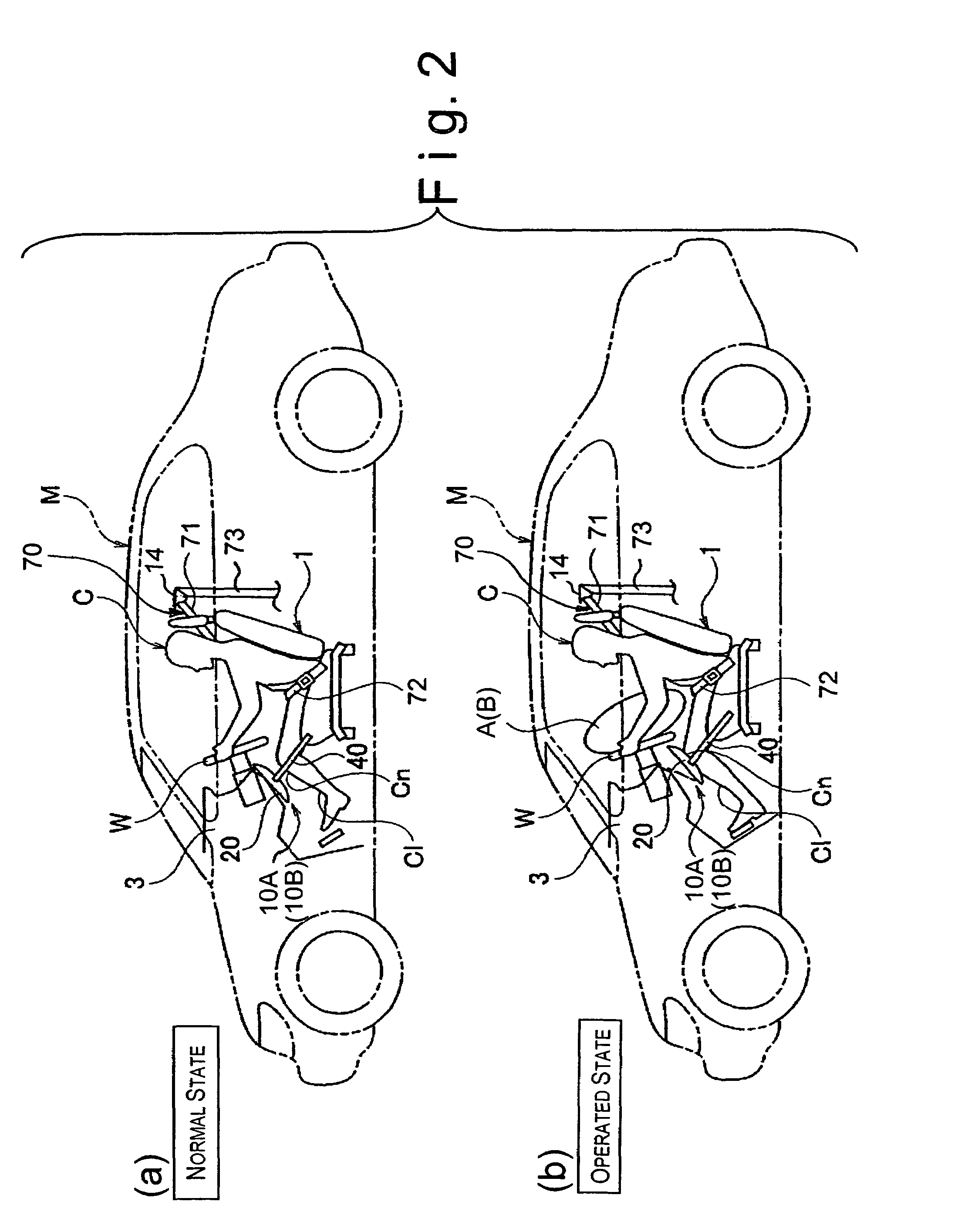
[0123]Referring now to FIGS. 22 to 29, a vehicle passenger restraining system in accordance with a second embodiment will now be explained. In view of the similarity between the first and second embodiments, the parts of the second embodiment that are identical to the parts of the first embodiment will be given the same reference numerals as the parts of the first embodiment. Moreover, the descriptions of the parts of the second embodiment that are identical to the parts of the first embodiment may be omitted for the sake of brevity.

[0124]The vehicle passenger restraining system of the second embodiment differs from the vehicle passenger restraining system of the first embodiment in that a retractor 150 of the second embodiment is further coupled to the seat belt member 70 so that the rearward movement of the knee bolster 20 is substantially synchronized with retraction of the seat belt member 70 during a collision in the second embodiment of the present invention. Moreover, the web...

third embodiment

[0176]Referring now to FIGS. 30 and 31, a vehicle passenger restraining system in accordance with a third embodiment will now be explained. In view of the similarity between the second and third embodiments, the parts of the third embodiment that are identical to the parts of the second embodiment will be given the same reference numerals as the parts of the second embodiment. Moreover, the descriptions of the parts of the third embodiment that are identical to the parts of the second embodiment may be omitted for the sake of brevity.

[0177]The vehicle passenger restraining system of the third embodiment is basically identical to the vehicle passenger restraining system of the second embodiment except that each of guide members 230 is provided with a locking mechanism 280 configured and arranged to allow rearward movement of the knee bolster 20 while preventing forward movement of the knee bolster 20. More specifically, the guide members 230 are basically identical to the guide membe...

fourth embodiment

[0184]Referring now to FIGS. 32 to 34, a vehicle passenger restraining system in accordance with a fourth embodiment will now be explained. In view of the similarity between the second and fourth embodiments, the parts of the fourth embodiment that are identical to the parts of the second embodiment will be given the same reference numerals as the parts of the second embodiment. Moreover, the descriptions of the parts of the fourth embodiment that are identical to the parts of the second embodiment may be omitted for the sake of brevity.

[0185]The vehicle passenger restraining system of the fourth embodiment is basically identical to the vehicle passenger restraining system of the second embodiment except that that transversely outside end of the belt member 140B is fixed to an outside guide section 330B of a guide member 330 such that the knee bolster 20 itself is spring loaded toward the front of the vehicle M without using the outside sliding anchor 42.

[0186]FIG. 32 is a perspecti...


PUM


Abstract

A vehicle passenger restraining system comprises a knee bolster, a bolster movement structure, a collision detecting section and a control section. The knee bolster is disposed in a front portion of a seat in a vehicle. The bolster movement structure is coupled to the knee bolster to apply a rearwardly directed pulling force to each transverse end of the knee bolster. The collision detecting section is configured and arranged to detect information relating to a collision of the vehicle and a probability of a collision of the vehicle. The control section is configured to operate the bolster movement structure based on the information from the collision detecting section.

Description

CROSS-REFERENCE TO RELATED APPLICATIONS[0001]This application claims priority under 35 U.S.C. § 119 to Japanese Patent Application Nos. 2004-346015 and 2005-211349. The entire disclosures of Japanese Patent Application Nos. 2004-346015 and 2005-211349 are hereby incorporated herein by reference.BACKGROUND OF THE INVENTION[0002]1. Field of the Invention[0003]The present invention relates to a vehicle passenger restraining system. More specifically, the present invention relates to a vehicle passenger restraining system having a knee bolster configured and arranged to restrain a forward movement of knees of a passenger during a collision.[0004]2. Background Information[0005]In a conventional vehicle passenger restraining system, when a vehicle undergoes a front collision, a forward movement of a passenger sitting in a passenger seat of the vehicle is restrained by a seat belt member including a lap belt and a shoulder belt. However, a portion of the passenger's body, i.e., a portion f...

Claims


Application Information

Patent Timeline
Patent Type & Authority Patents(United States)
IPC IPC(8): B60R21/04B60R21/205
CPCB60R21/045B60R21/013B60R2021/0051
Inventor PAL, CHINMOYKOBAYASHI, IZUMIMAKITA, MASASHI
Owner NISSAN MOTOR CO LTD
Why Eureka
Try Eureka