Seatbelt system for vehicle, and control method for seatbelt system

a seatbelt and vehicle technology, applied in the direction of seatbelt control systems, vehicle components, vehicle safety belts, etc., can solve the problems of increased seatbelt tension, reduced torque required from the motor, and seatbelt slack, etc., to achieve a large current, increase the size of the motor, and generate high torque

Active Publication Date: 2020-04-16
TOYOTA JIDOSHA KK
View PDF0 Cites 2 Cited by
  • Summary
  • Abstract
  • Description
  • Claims
  • Application Information

AI Technical Summary

Benefits of technology

[0014]With the above configuration, a required torque from the motor is restricted when the seatbelt is taken up by the driving force of the motor in the event of a minor co

Problems solved by technology

However, even in the event of a minor collision, a collision acceleration is applied to an occupant to displace the occupant, with the result that the tension of the seatbelt increases.
Therefore, with the above configuration, a required torque from the motor is restricted when

Method used


Image

  • Seatbelt system for vehicle, and control method for seatbelt system
  • Seatbelt system for vehicle, and control method for seatbelt system
  • Seatbelt system for vehicle, and control method for seatbelt system

Examples


first embodiment

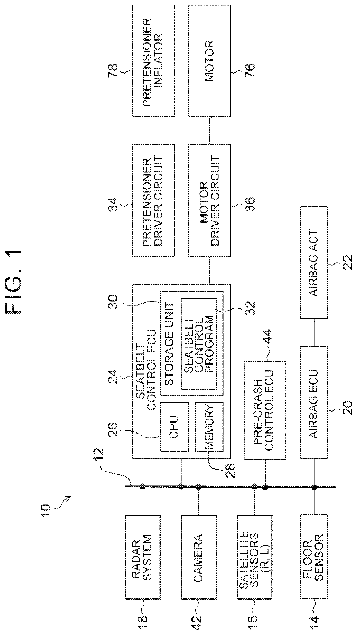
[0033]In the first embodiment, the floor sensor 14 is an example of a detector, and the seatbelt control ECU 24, the pretensioner driver circuit 34, and the motor driver circuit 36 are an example of an electronic control unit.

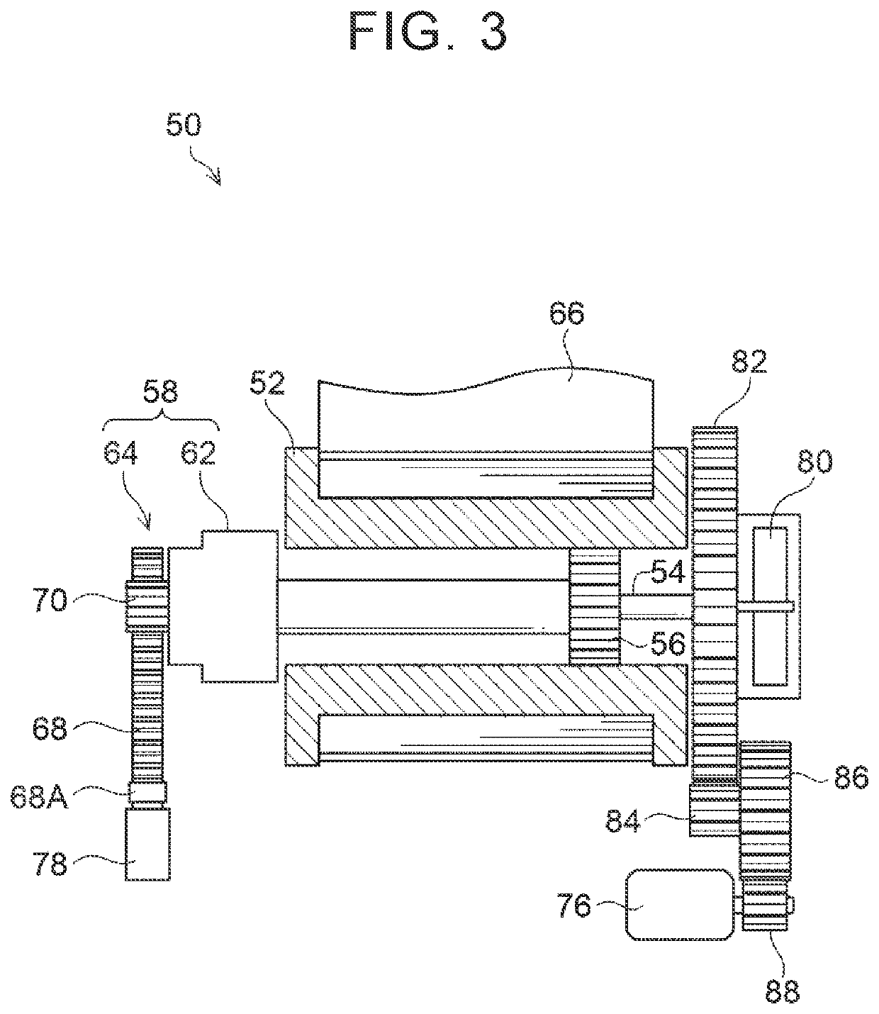
[0034]As shown in FIG. 3, a seatbelt take-up device 50 includes a spool 52 that takes up a seatbelt 66. The spool 52 is hollow at its center. A torsion bar 54 is provided in the hollow portion. The torsion bar 54 is coupled to the spool 52 via a coupling member 56 at a position shifted toward a spring mechanism 80 (described later) from the center of the spool 52 in an axial direction, and functions as the rotary shaft of the spool 52. The torsion bar 54 has different diameters on both sides of the coupling member 56. In the present embodiment, a pretensioner unit 58 side of the torsion bar 54 is greater in diameter than a spring mechanism 80 side of the torsion bar 54.

[0035]The torsion bar 54 may have a structure such that the spring mechanism 80 side and the ...

second embodiment

[0055]As shown in FIG. 6, a seatbelt control process proceeds to step 114 when the determination of step 106 is negative. In step 114, the seatbelt control ECU 24 determines whether a predetermined time t1 has elapsed from when the collision has been detected (from when the determination of step 104 is affirmative), step 114 is repeated until the determination is affirmative. As an example, as shown in FIG. 5, a time corresponding to a time required from occurrence of a minor collision until the deceleration G reduces to less than or equal to the second threshold Gth2 is set for the predetermined time t1.

[0056]When the predetermined time t1 has elapsed, the determination of step 114 is affirmative, and the process proceeds to step 118. In step 118, the motor 76 is driven in the direction to take up the seatbelt 66. In this stage, the tension of the seatbelt 66 has been reducing, and the motor 76 is able to take up the seatbelt 66 with a low torque. Therefore, an increase in the siz...


PUM


Abstract

A seatbelt system includes a take-up device configured to take up a seatbelt, and an electronic control unit configured to, when any one of first and second conditions is satisfied, cause a motor to take up the seatbelt. In the first condition, after occurrence of a collision whose physical quantity detected by a detector configured to detect the physical quantity associated with a magnitude of the collision is less than or equal to a first threshold, the physical quantity decreases to less than or equal to a second threshold. In the second condition, after occurrence, of a collision whose physical quantity is less than or equal to the first threshold, a first predetermined time elapses, which is estimated to be equivalent to a decrease in the physical quantity to less than or equal to the second threshold.

Description

CROSS-REFERENCE TO RELATED APPLICATIONS[0001]This application claims priority to Japanese Patent Application No. 2018-193769 filed on Oct. 12, 2018, which is incorporated herein by reference in its entirety including the specification, drawings and abstract.BACKGROUND1. Technical Field[0002]The disclosure elates to a seatbelt system for a vehicle, and a control method for a seatbelt system.2. Description of Related Art[0003]Japanese Unexamined Patent Application Publication No. 2011-126332 (JP 2011-126332 A) describes a technique for making it possible to take up a seatbelt in the event of a minor collision in an initial stage of multiple collisions by, when it is determined that an acceleration represented by an impact signal is less than a predetermined value, driving a motor forward to take up the seatbelt.SUMMARY[0004]The technique described in JP 2011-126332 A immediately takes up a seatbelt as a collision occurs. However, even in the event of a minor collision, a collision acc...

Claims


Application Information

Patent Timeline
IPC IPC(8): B60R21/0134
CPCB60R2021/01279B60R2021/01013B60R2021/01272B60R21/0134B60R2021/01317B60R22/343B60R22/46B60R22/48B60R21/013
Inventor NEZAKI, TAKUYASUGIYAMA, MOTOKIKOMENO, FUMIHITO
Owner TOYOTA JIDOSHA KK
Why Eureka
Try Eureka