
Class DE driving amplifier for piezoelectric actuators

a piezoelectric actuator and driving amplifier technology, applied in piezoelectric/electrostrictive device details, piezoelectric/electrostrictive/magnetostrictive devices, piezoelectric/electrostriction/magnetostriction machines, etc., can solve problems such as energy consumption related to piezoelement driving, and achieve good efficiency and minimize noise

Inactive Publication Date: 2009-06-30
NOKIA CORP
View PDF14 Cites 5 Cited by
  • Summary
  • Abstract
  • Description
  • Claims
  • Application Information

AI Technical Summary

Benefits of technology

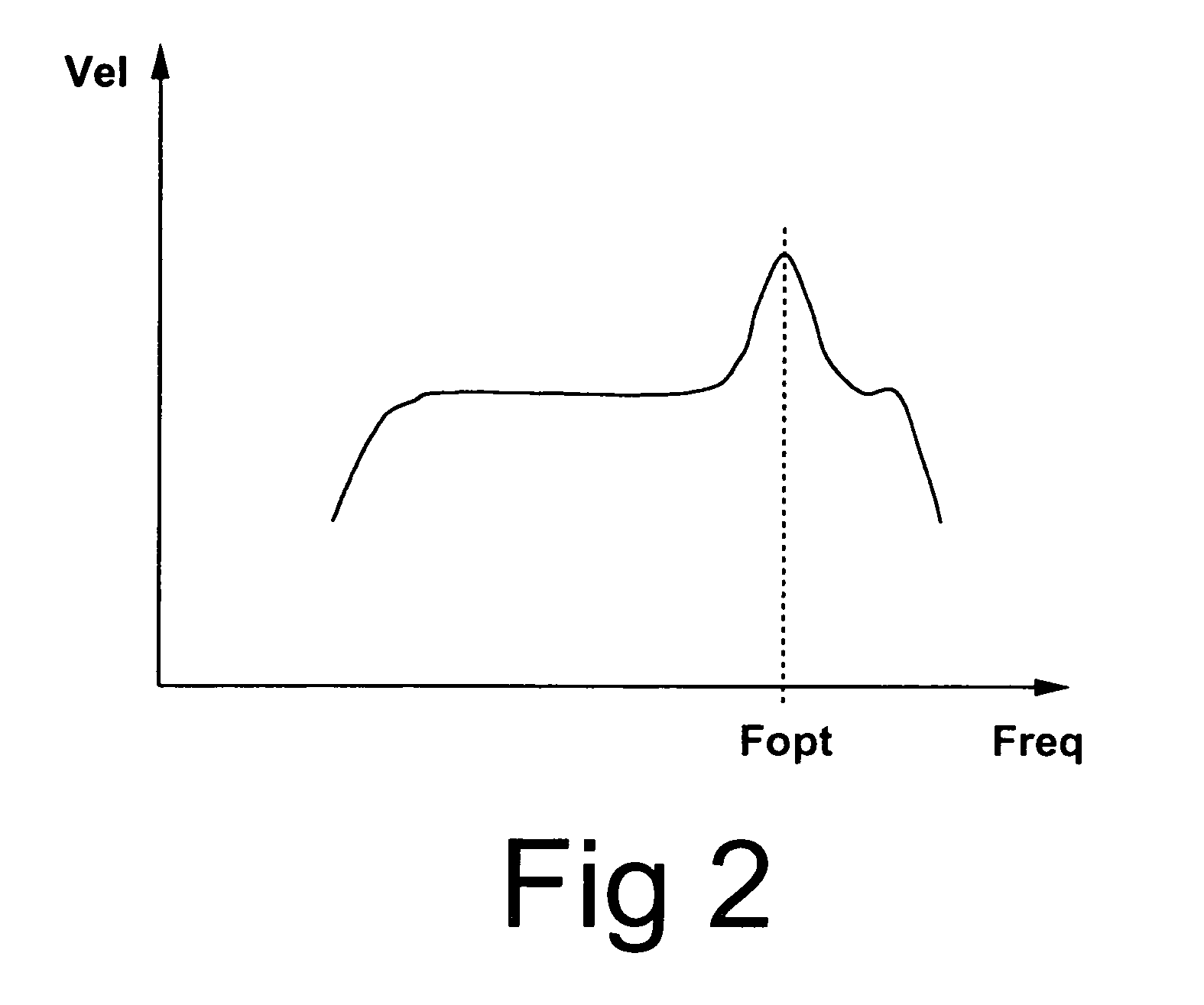
[0028]According to another embodiment of the invention, a further criterion for selecting the optimum driving frequency Fopt is minimizing the noise generated by the piezo-actuator or -drive.
[0029]According to the present invention, optimum performance of the piezo-elements is obtained, irrespective of manufacturing tolerances and temperature drift of operating parameters. Further, the piezo-elements are driven with good efficiency. The improvement is significant when compared with prior art methods in which the design is based on fixed driving frequency, said fixed driving frequency being determined on the basis of average component parameters in typical operating conditions.

Problems solved by technology

Further, in mobile systems, the available power supply is typically a battery with a limited capacity.
Therefore energy consumption related to the driving of piezo-elements is a problem especially in mobile systems.

Method used


Image

  • Class DE driving amplifier for piezoelectric actuators
  • Class DE driving amplifier for piezoelectric actuators
  • Class DE driving amplifier for piezoelectric actuators

Examples


Embodiment Construction

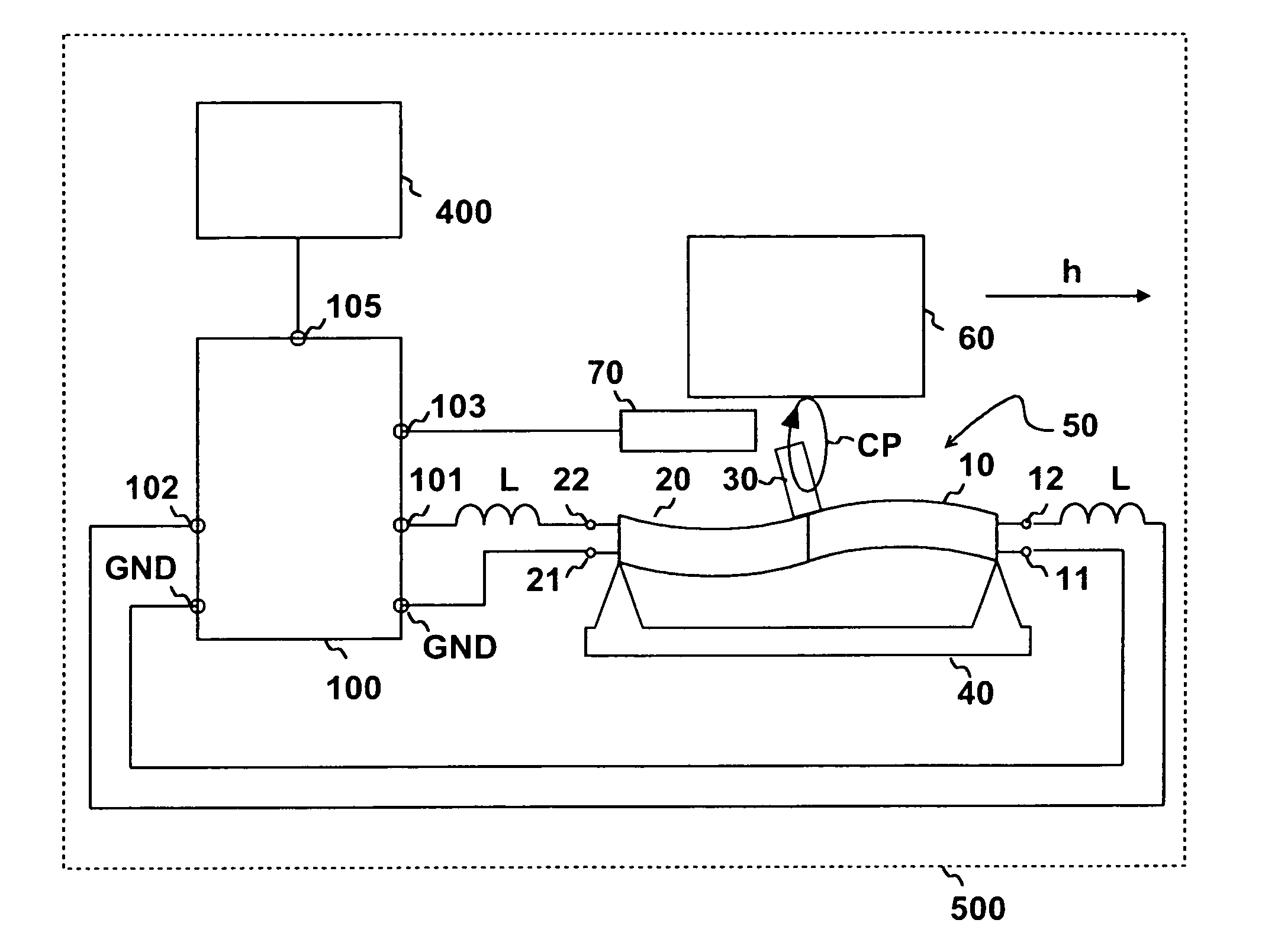
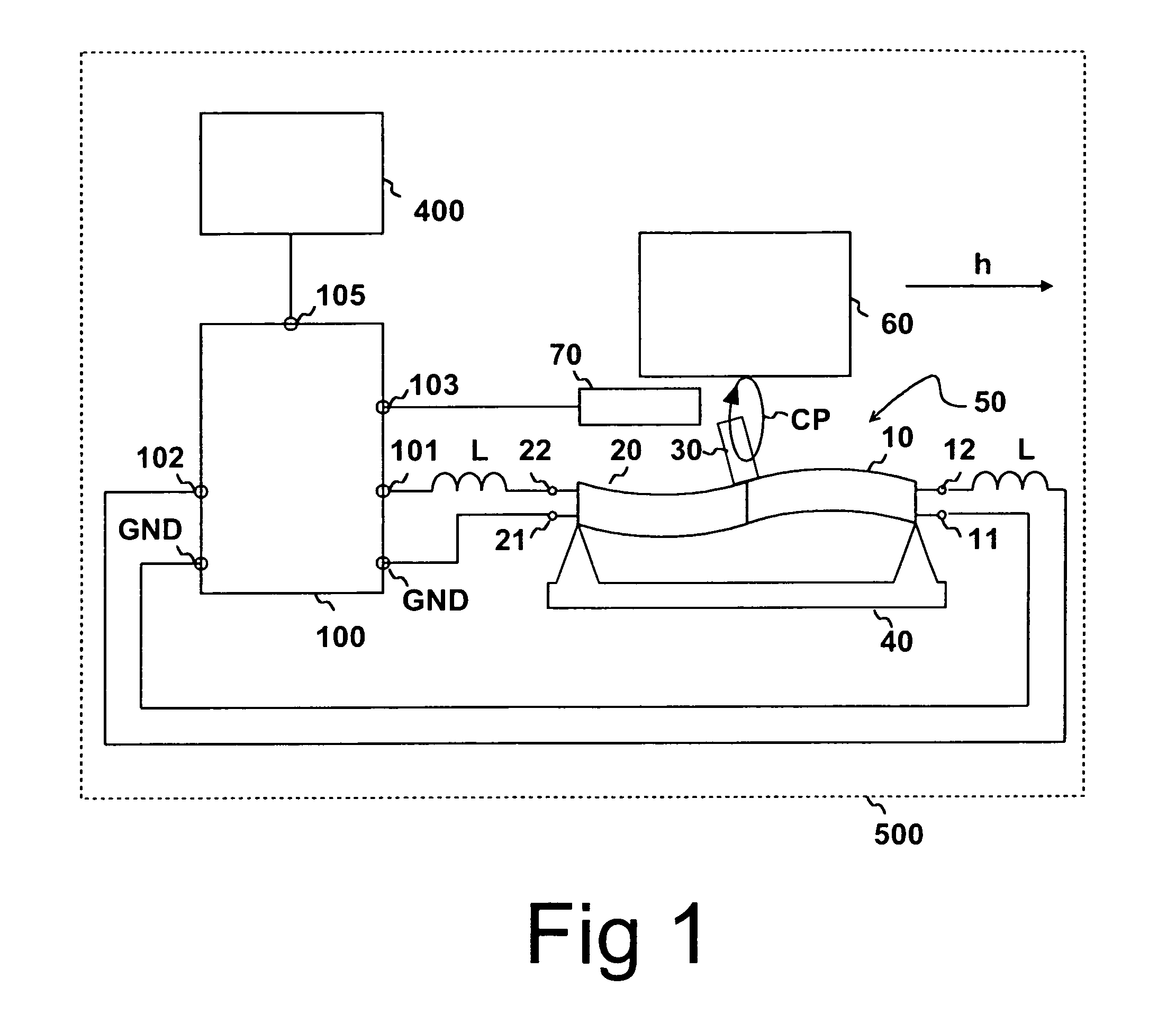
[0040]Referring to FIG. 1, a device 500 according to the present invention comprises a driving device 100. The outputs 101, 102 of the driving device 100 are coupled to the connecting nodes 12, 22 of a piezo-electric actuator 50 by inductive elements L. The driving device is controlled by a control unit 400, which communicates with the driving device 100 by a data node 105. GND denotes ground voltage.

[0041]The piezo-electric actuator 50 may comprise two independently deflectable piezo-elements 10, 20, which are connected together. A protrusion 30 is attached near the connection point of said two piezo-elements 10, 20. The piezo-elements 10, 20 are supported by a support 40, which allows deflection of said piezo-elements 10, 20. The degree of deflection of each piezo-element 10, 20 is changed when a voltage is applied between voltage nodes 11, 12, 21, 22 of said piezo-elements 10, 20. The piezo-actuator is preferably implemented using bimorphs. Such bimorphs are described, for exampl...


PUM


Abstract

The invention relates to a method and device for driving a piezo-electric actuator. A driving voltage is coupled to the piezo-electric actuator by an inductive element coupled in series with the piezo-electric actuator. The piezo-electric actuator is adapted to move an object. The frequency of the driving voltage coupled to the piezo-electric actuator is varied and the velocity of the object is recorded as a function of the frequency. Subsequently, an optimum frequency is determined and the frequency of the driving voltage is adjusted to be substantially equal to the optimum frequency. The optimum frequency is preferably associated with a maximum obtainable velocity of the object.

Description

CROSS-REFERENCE TO RELATED APPLICATIONS[0001]This application claims priority under 35 USC §119 to Finnish Patent Application No. 20045263 filed on Jul. 2, 2004.FIELD OF THE INVENTION[0002]The present invention relates to a piezo-element driving device and a method for driving piezo-elements. The present invention relates also to a device comprising a piezo-element driving device.BACKGROUND OF THE INVENTION[0003]Piezo-electric actuators are used in imaging systems to adjust the positions of zoom and focusing lens systems. Piezo-electric actuators are also used in other systems to move small objects. Driving devices providing suitable driving voltages are required to operate said piezo-electric actuators. Piezo-electric actuators are implemented by using one or more piezo-elements, which are deflected, expanded or contracted when coupled to an activating voltage.[0004]An aspect in mobile devices is that the voltage of an available power supply is typically lower than the optimum driv...

Claims


Application Information

Patent Timeline
Patent Type & Authority Patents(United States)
IPC IPC(8): H01L41/09H01L41/04H04R
CPCH02N2/001H02N2/008
Inventor OLLILA, MIKKO
Owner NOKIA CORP
Learn More