Wireless tag scanning system

a scanning system and tag technology, applied in the field of wireless tag scanning system, can solve the problems of inability to detect the position of a management object with high resolution, increase the number of parts, and increase the cost of the scanning system, and achieve the effect of low cost and high resolution

Inactive Publication Date: 2009-06-30
TOSHIBA TEC KK
View PDF8 Cites 0 Cited by
  • Summary
  • Abstract
  • Description
  • Claims
  • Application Information

AI Technical Summary

Benefits of technology

[0009]According to embodiments of the present invention, an object of the present invention is to enable position detection with high resolution and provide an inexpensive scanning system by moving an antenna section of a wireless tag scanning device, whose directivity is selectively directed, in a direction equal to that of wireless tags which are lined up in one direction, and scanning the wireless tags in synchronization with the move.

Problems solved by technology

However, the spatial resolution of the place is determined in an area where an electromagnetic wave generated from an antenna arrives, and the position of a management object cannot be detected with high resolution.
Furthermore, when preparing a plurality of antennas, the number of parts increases, which undesirably increases cost (refer to Jpn. Pat. Appln. Laid-Open Publication No.

Method used


Image

  • Wireless tag scanning system
  • Wireless tag scanning system
  • Wireless tag scanning system

Examples


Embodiment Construction

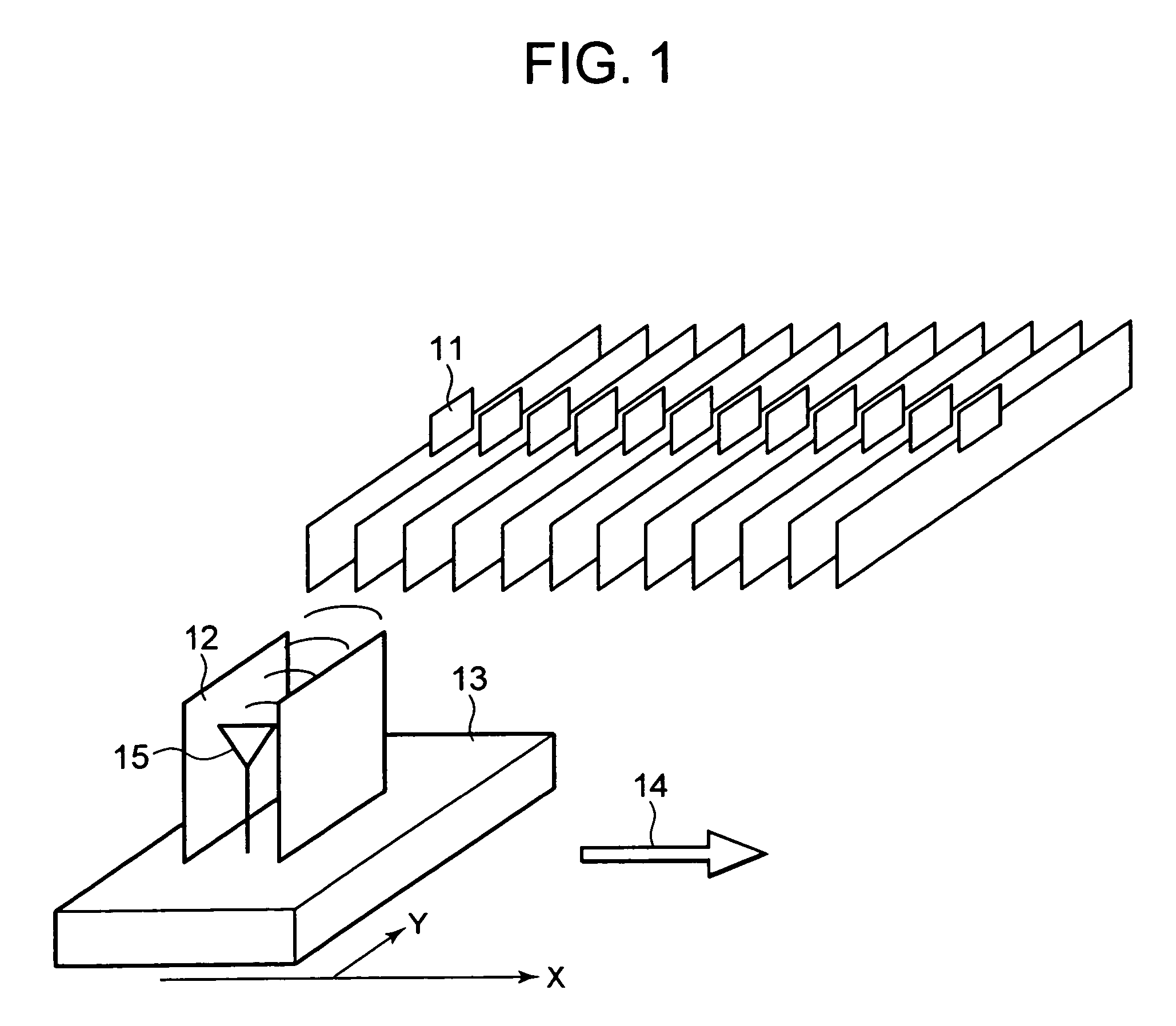
[0014]The present invention will further be described below with reference to the accompanying drawings. FIG. 1 shows one embodiment of the present invention.

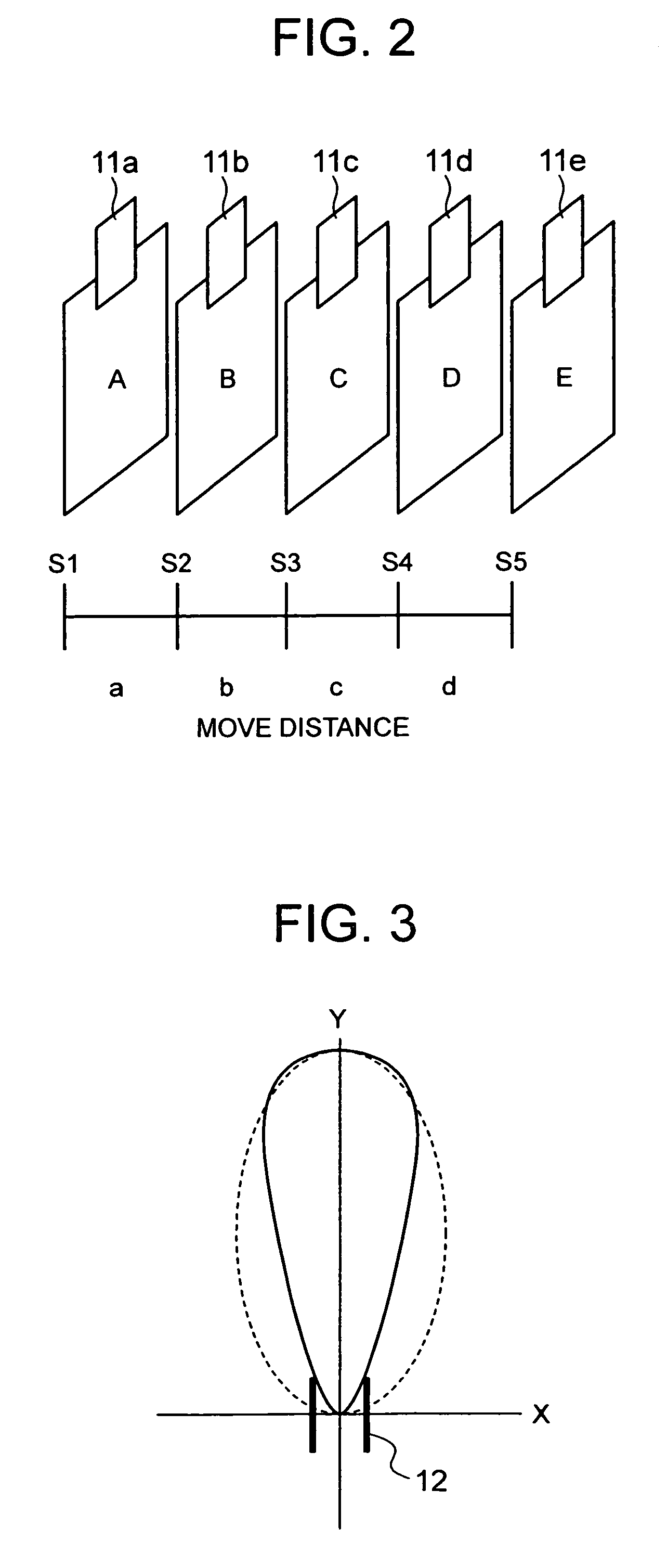
[0015]In FIG. 1, the referenced numeral 11 indicates a wireless tag, 12 indicates a shield member that controls the directivity of an antenna, 13 indicates a movable table for moving an antenna, 14 indicates a moving direction (moving means), and 15 indicates an antenna.

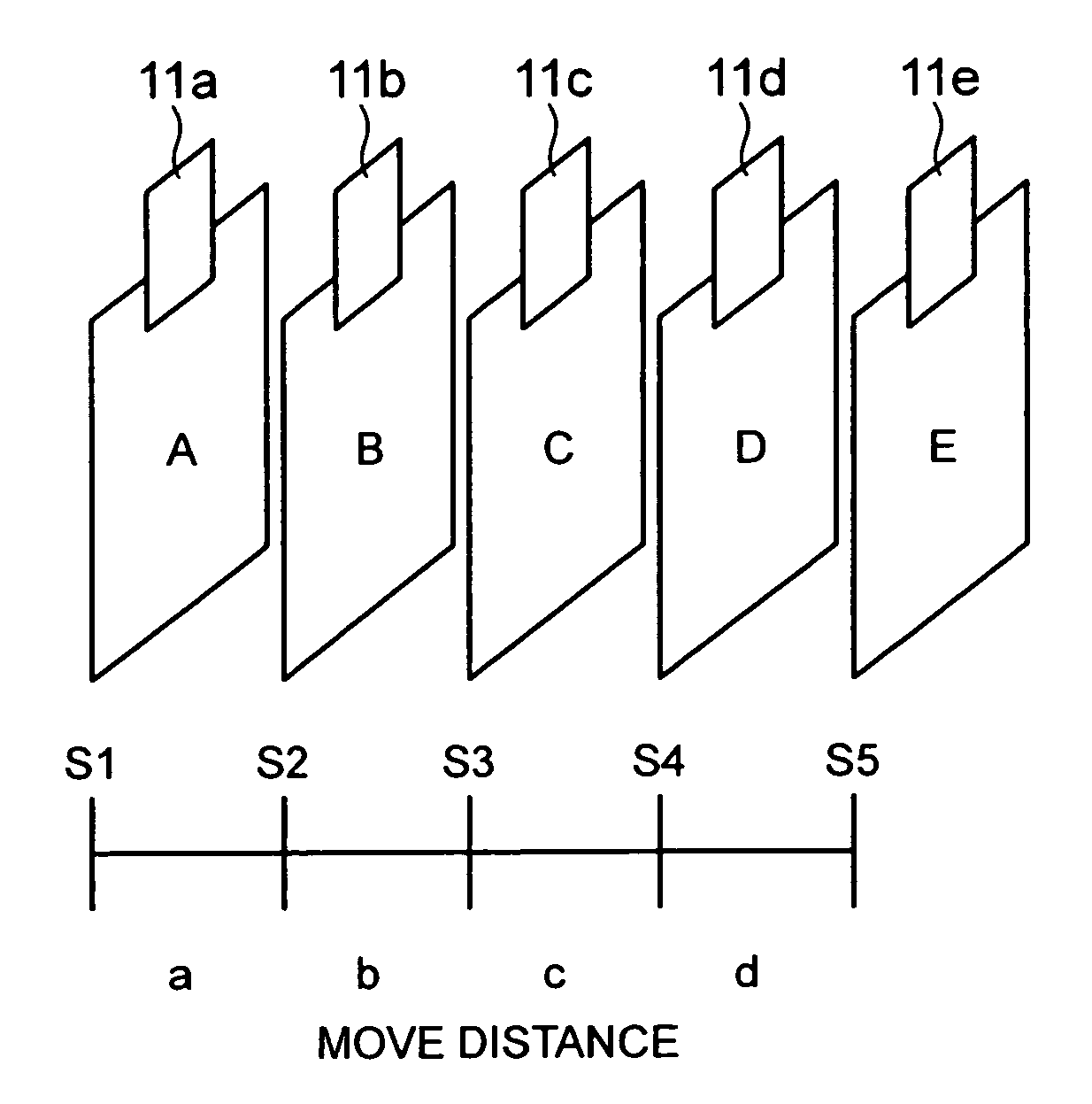
[0016]The wireless tags 11 are attached to management objects with their directivity aligned in the direction of the antenna 15. Then, the management objects are arranged on the X axis with equal spaces situated therebetween (the spaces do not necessarily have to be equal).

[0017]The movable table 13 that can move in the X axis direction has arranged thereon the antenna 15 of a wireless tag scanning device. The antenna 15 has its electromagnetic wave in the X-axis direction blocked by the use of at least two shield members 12 so as to selectively direct its direc...


PUM


Abstract

Under the step management of a stepping motor, a move distance of an antenna of a wireless tag scanning device is calculated, and wireless tags are scanned in synchronization with a step move amount. The antenna controls its directivity using shield members etc., and lowers electromagnetic susceptibility in the moving direction. Accordingly, it becomes possible to detect a wireless tag located on a certain position, enabling position management with high resolution.

Description

CROSS-REFERENCE TO RELATED APPLICATIONS[0001]This application is based upon and claims the benefit of priority from the prior Japanese Patent Application No. 2005-91396, filed on 28th Mar., 2005; the entire contents of which are incorporated herein by reference.BACKGROUND OF THE INVENTION[0002]1. Field of the Invention[0003]The present invention relates to a wireless tag scan system that scans data of a wireless tag without wires.[0004]2. Description of the Related Art[0005]Recently, systems using radio frequency identification (RFID) have been a focus of attention. It is possible to ascertain the presence of a management object in an area by attaching a wireless tag to the management object and scanning wireless tag identification information thereof. However, in case there exist a plurality of management objects, when finely differentiating their positional information, wireless tag scanning devices have to be arranged by the number of management sections, or a plurality of antenn...

Claims


Application Information

Patent Timeline
Patent Type & Authority Patents(United States)
IPC IPC(8): H04Q5/22
CPCG06K17/00G06K2017/0051
Inventor ISHIKAWA, ATSUSHI
Owner TOSHIBA TEC KK
Why Eureka
Try Eureka