Latch actuator system

a technology of latch actuator and actuator, which is applied in the direction of movable seats, vehicle components, vehicle arrangements, etc., can solve the problems of complicated resetting of dual-mode actuators, uneconomical cost of motors and gear reducers, and interference of one mode of actuation with the other mod

Inactive Publication Date: 2009-07-07
LEAR CORP
View PDF23 Cites 27 Cited by
  • Summary
  • Abstract
  • Description
  • Claims
  • Application Information

AI Technical Summary

Benefits of technology

[0012]According to other aspects of the present invention, the trigger may have a housing that encloses a shiftable element that is attached to the link. The shiftable element retracts the link in the first direction when the trigger is switched from the locked state to the released state. A manually engaged handle may be provided on the latch such that the link is not under tension when the latch is in the locked position to permit the latch to be manually moved to the released position. The link may be a cable and the actuator may further comprise a rotary cam guide about which the cable is entrained. The rotary cam guide may control the tension applied by the cable to the latch. A reset tension may be required to reset the trigger and the tension in the cable may be reduced to a level below the reset tension when the latch is in the locked position. The trigger may have a linearly movable armature that is held in the locked position by a locking member such that the locking member restrains an armature spring that applies a retraction force to the link in the first direction when the trigger is released.
[0015]According to another aspect of the present invention, a vehicle seat that has a seat base and a seat back that pivots relative to the seat base to facilitate ingress and egress to the vehicle. The vehicle seat comprises a hinge connecting the seat back to the seat base. A latch retains the seat back in a selected position with the latch having a latched condition in which the seat back is held in the generally vertical, but rearwardly inclined, orientation relative to the seat base. The latch may be released so that the seat back is pivoted to a position overlying the seat base. A trigger may be used to cause the latch to be switched between the latched condition and the released condition. The trigger is connected to the latch by a link that is connected between the latch and the trigger. A power spring is connected between the seat back and the seat base that biases the seat back to move toward the position in which it overlies the seat base. The latch in the latched condition functions to resist the biasing force of the power spring. When the latch is released, the seat back is moved by the power spring to the position in which it overlies the seat base. A cable guide cam is secured to the power spring for tensioning and guiding the cable as the seat back is moved between the latched condition and the released condition. The trigger selectively acts on the link in the latched condition to move the link in a first direction to release the latch which in turn releases the seat back to be moved by the power spring to the position overlying the seat base. Movement of the seat back relative to the seat base causes the link to exert a force on the link in a second direction to reset the trigger.

Problems solved by technology

While this approach is effective, the cost of a motor and gear reducer may be uneconomical in many applications.
One problem with such dual actuation latches is that one mode of actuation may interfere with the other mode.
In addition, resetting the dual mode actuator may be complicated if both modes of actuation are not accommodated by the reset mechanism.
While these types of systems have been developed, the cost of the motor and gear reducer may make such systems uneconomical.

Method used


Image

  • Latch actuator system
  • Latch actuator system
  • Latch actuator system

Examples


Embodiment Construction

)

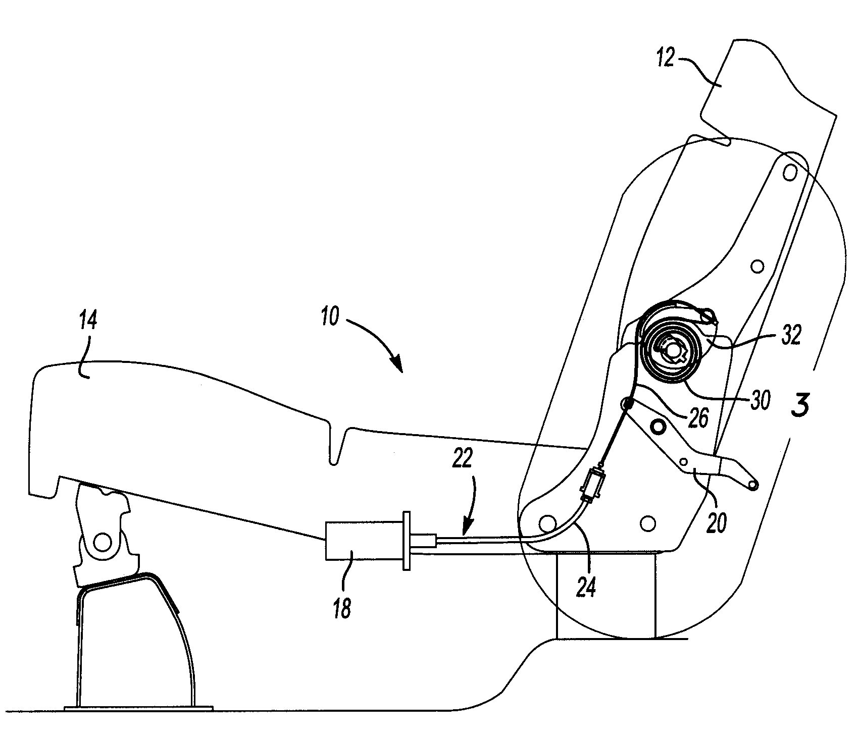
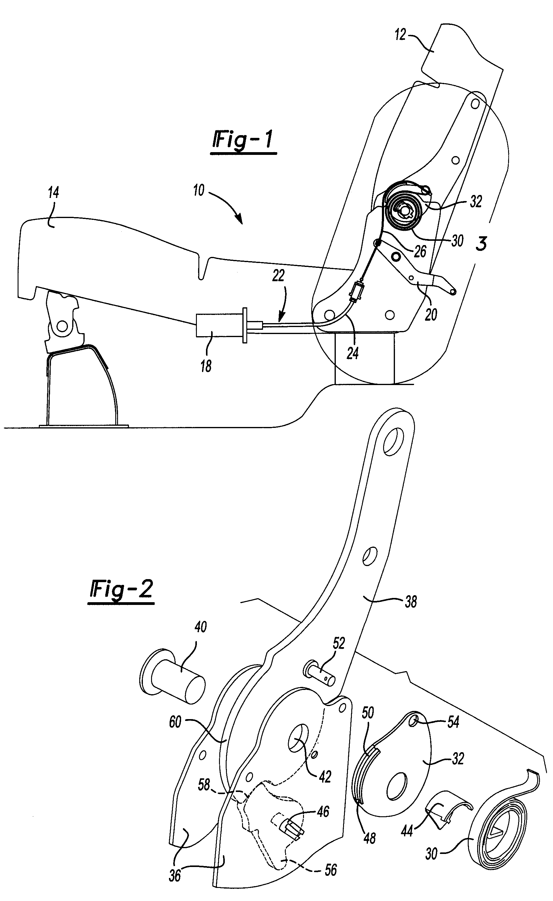
[0029]Referring to FIG. 1, a vehicle seat 10 is illustrated that has a seat back 12 and a seat base 14. An actuator 18, or trigger, is illustrated as being attached to the seat base 14. However, it should be understood that the actuator 18 could be secured to another location on the vehicle or seat support structure. A latch lever 20 is connected to the actuator 18 by a Bowden cable 22, or link. The Bowden cable 22 includes a sleeve 24 that encloses a wire 26 so that the wire 26 is axially moveable relative to the sleeve. The Bowden cable 22 is also connected to a power spring 30. The cable 22, or link, passes over a cable guide cam 32 that is rotatable with the power spring 30.

[0030]Referring to FIG. 2, one type of hinge mechanism is shown in greater detail in an exploded perspective view that shows one way of connecting the seat back to the seat base 14. It should be understood that other types of hinge mechanisms may be adapted to include the latch actuator system of the present...


PUM


Abstract

An actuator for a latch assembly for securing a latched member that is linked to a trigger. The trigger may be a shape memory alloy actuating element that is actuated in response to receiving an electrical signal. The trigger may be mechanically reset to a locked state by the latched member. A method of operating the latch is also disclosed wherein the trigger is actuated in response to an electrical signal resulting in a force being applied in a first direction to a cable that connects the trigger to release the latch. The trigger is reset by exerting mechanical force on the trigger in the opposite direction. The latch system may be applied to a vehicle seat having a seat back that pivots relative to a seat base to allow the seat back to pivot over the seat base.

Description

BACKGROUND OF THE INVENTION[0001]1. Field of the Invention[0002]The present invention relates to a remote actuator for a latch that releases a latched member for movement that may be automatically reset by moving the latched member.[0003]2. Background Art[0004]Actuators are devices that cause an apparatus to operate. Latches are devices that are used to grasp or lock an object, as with a catch and a lever, or the like. An actuator may be used to release or engage a latch. Some actuators may be remotely connected to a latch to allow for operation of the latch from a distance.[0005]Latches are used in a wide variety of applications. For example, latches may be provided as a part of a machine, on building doors or windows, or in vehicles. Latches that can be reset have the advantage that they can be used repeatedly. One way to provide a latch that can be reset is to provide an actuator that operates a motor and gear reducer to release the latch by forward rotation of the motor and rese...

Claims


Application Information

Patent Timeline
Patent Type & Authority Patents(United States)
IPC IPC(8): B60N2/48
CPCB60N2/206B60N2/0224B60N2/20
Inventor NATHAN, JOHN F.MAUE, H. WINSTON
Owner LEAR CORP
Why Eureka
Try Eureka