Lamp assembly

a technology for assembly and lamps, applied in the direction of lighting support devices, coupling device connections, lighting and heating apparatuses, etc., can solve the problems of requiring additional time and requiring adjustment of rotational positions, and achieve the effect of convenient assembly, fast electrical connection and fast electrical connection

Inactive Publication Date: 2009-07-07
LEDTECH ELECTRONICS CORP
View PDF5 Cites 104 Cited by
  • Summary
  • Abstract
  • Description
  • Claims
  • Application Information

AI Technical Summary

Benefits of technology

[0007]The object of the present invention is therefore to provide a lamp assembly, employing a tube and an electrical socket, which can accomplish fast electrical connection between the tube and the socket. Terminal lugs of the tube can contact with corresponding connectors immediately upon insertion of the tube into the electrical socket. Thereby, fast electrical connection and convenient assembly are achieved.
[0011]The contact plate of the socket is sufficiently large so that it electrically connects to the terminal lugs of the tube as soon as the tube is inserted. Thus, the assembly becomes faster and more convenient.

Problems solved by technology

The necessity to rotate the tubes after their insertion creates an inconvenience during the assembly and requires additional time.
However, LED tubes provide lighting only at a specific angle and thus can require adjustment of their rotational position.

Method used


Image

  • Lamp assembly
  • Lamp assembly
  • Lamp assembly

Examples


Embodiment Construction

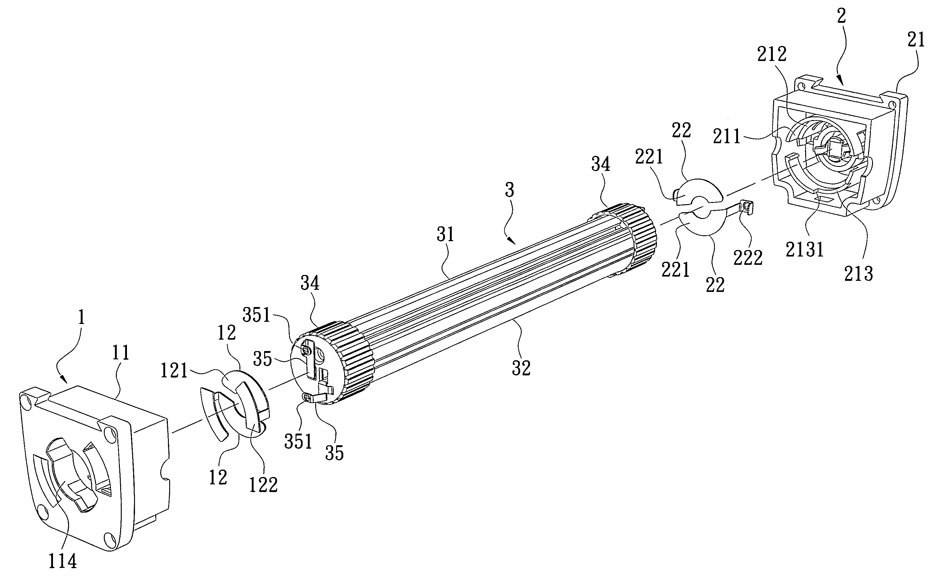
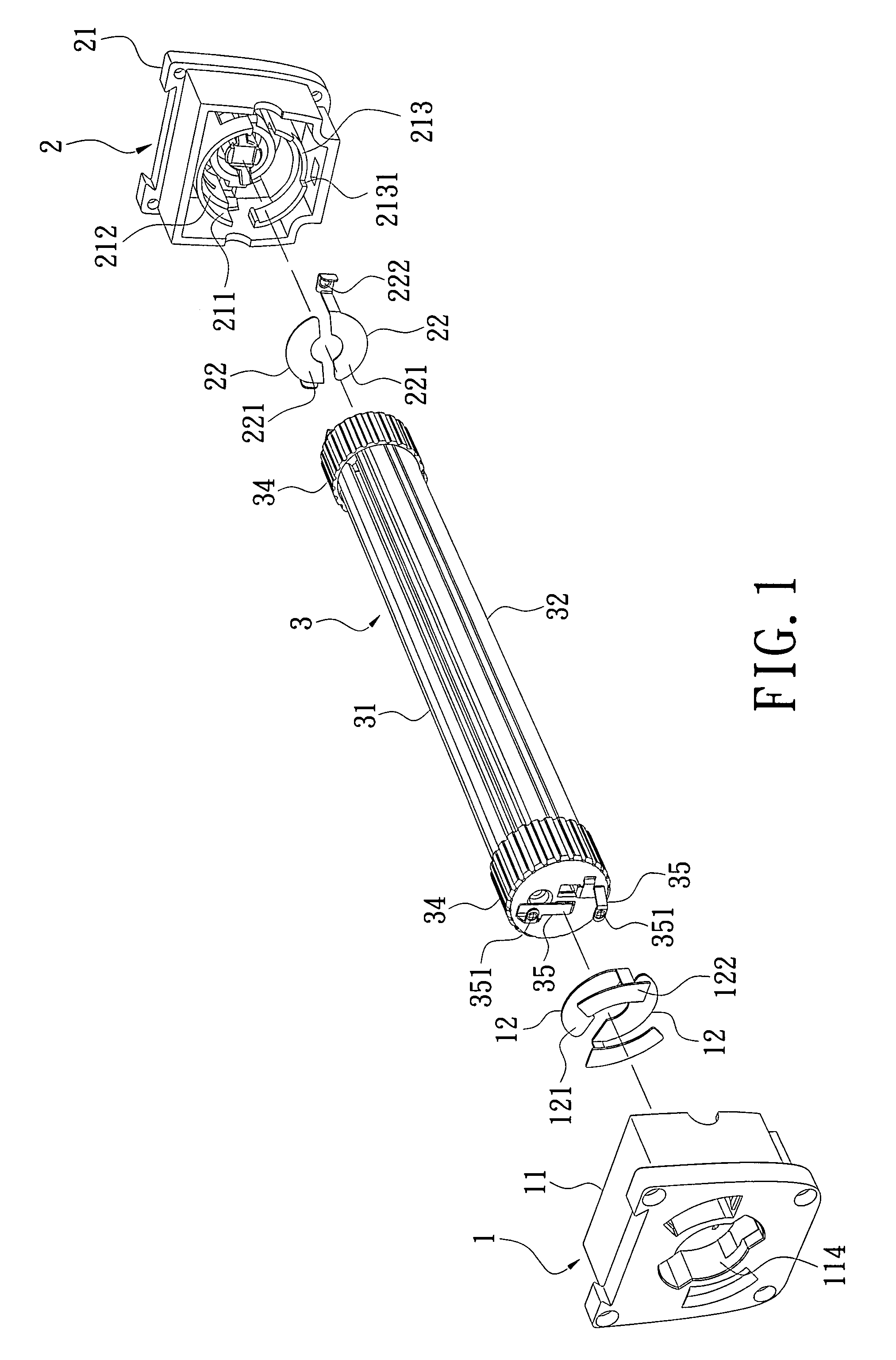
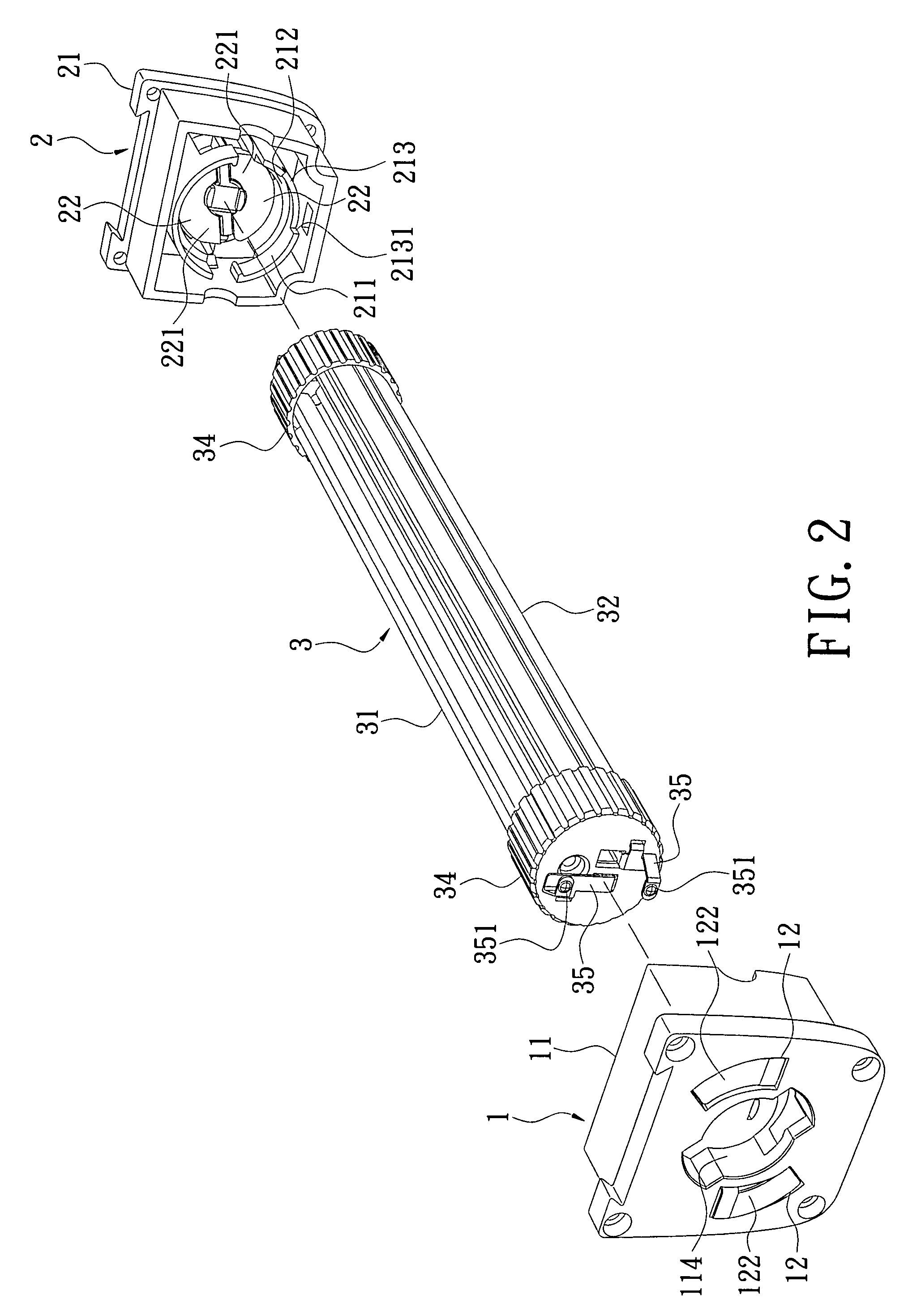
[0024]Referring to FIGS. 1 to 4, a lamp assembly disclosed in the present invention includes a first electrical socket 1, a second electrical socket 2 and a tube 3. The first electrical socket 1 includes a first insulating body 11 and two connectors 12. The first insulating body 11 is made of synthetic material. The first insulating body 11 is made integrally in one piece or as an assembly. The first insulating body 11 has a first insertion hole 111, which has a round shape, formed therein for receiving one end of the tube 3. The tube 3 is rotatable in the first electrical socket 1. The first insulating body 11 further includes a first inner support surface 112 annularly surrounding the first insertion hole 111, and the end of the tube 3 is sustained by the first inner support surface 112. The first insulating body 11 includes a first orientation notch 113 at the edge of the first insertion hole 111, and two first obstruction surfaces 1131 formed at two ends of the first orientation...


PUM


Abstract

A lamp assembly includes at least one electrical socket and a tube. The electrical socket includes an insulating body and two connectors set in the insulating body. The insulating body has an insertion hole. The two connectors have a contact plate exposed in the insertion hole. The tube has two terminal lugs disposed at least at one end thereof. The end of the tube and the two terminal lugs are inserted and installed in the insertion hole of the electrical socket. The terminal lugs electrically contact the contact plate of the connector. The end of the tube installed in the insertion hole is rotatable, the lighting angle can be adjusted. Thus, the tube can be electrically connected with the electrical socket quickly, the tube is lit instantly, and the tube can be rotated to adjust the lighting angle.

Description

BACKGROUND OF THE PRESENT INVENTION[0001]1. Field of the Present Invention[0002]The present invention relates to a lamp assembly, and particularly relates to an LED lamp assembly that is capable of adjusting the lighting angle by rotating a tube thereof.[0003]2. Background of the Present Invention[0004]Most conventional fluorescent lamps or LED lamps, are assembled by inserting terminal lugs of a tube into electrical sockets. A socket assembly is disclosed in Taiwan Patent No. I266025, entitled “Connection base capable of insertions at opposite faces”, Published on 11, Nov., 2006. The socket assembly includes two sockets and a space between them where a fluorescent tube can be clamped. The two sockets are of identical structure and are symmetrical to each other. The sockets include two symmetrical, curved slots at their sides facing the tube, and two rotatable connectors disposed in the slots respectively. The connectors have two contact plates extending from them. The two contact p...

Claims


Application Information

Patent Timeline
Patent Type & Authority Patents(United States)
IPC IPC(8): F21S4/00H01R33/08
CPCF21K9/17F21V14/02F21K9/58F21Y2103/00F21Y2101/02F21K9/272F21K9/65F21Y2103/10F21Y2115/10
Inventor KUO, SHU-HSIUNGLIU, YEN-FULIU, YU-YANG
Owner LEDTECH ELECTRONICS CORP
Why Eureka
Try Eureka