

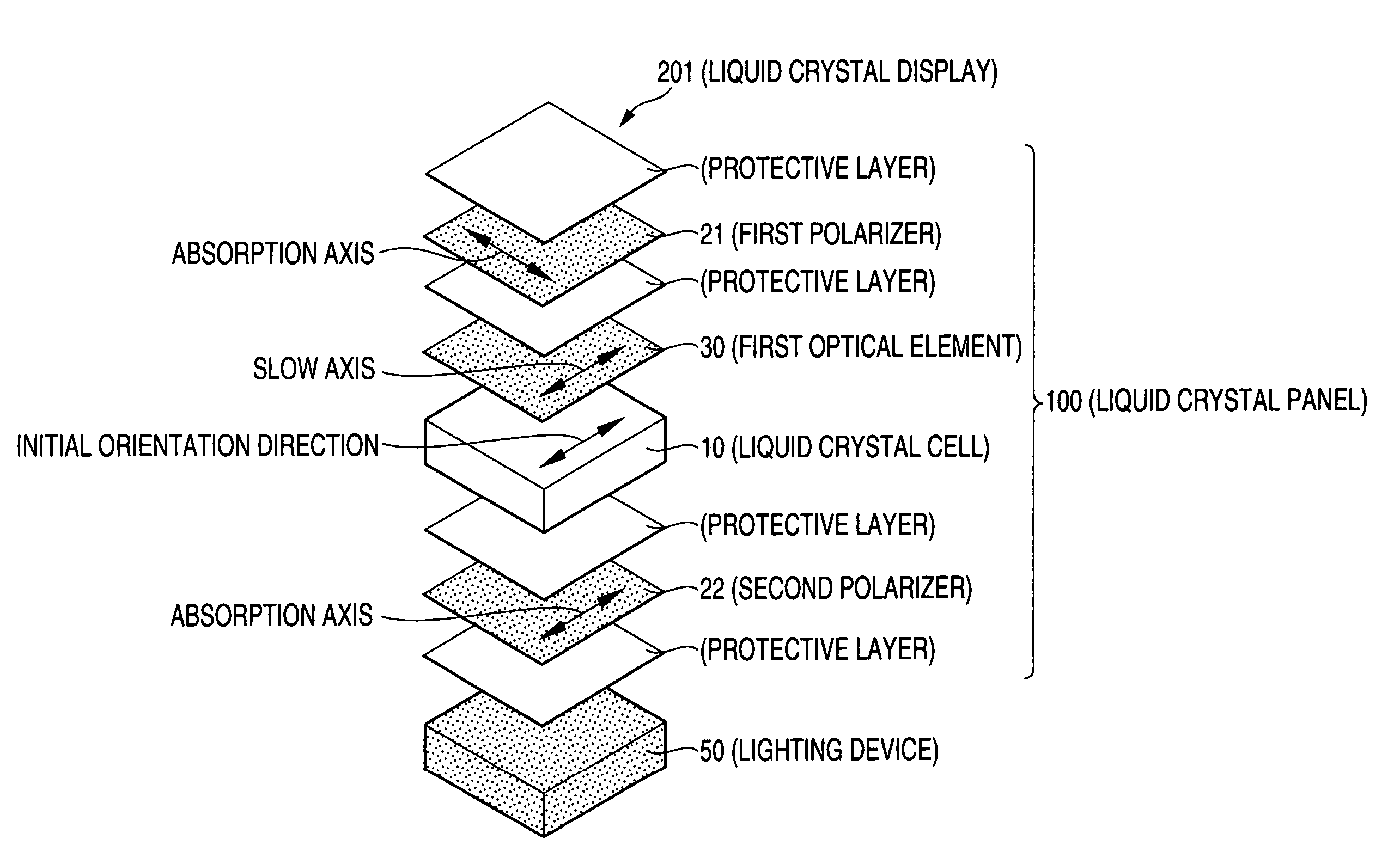
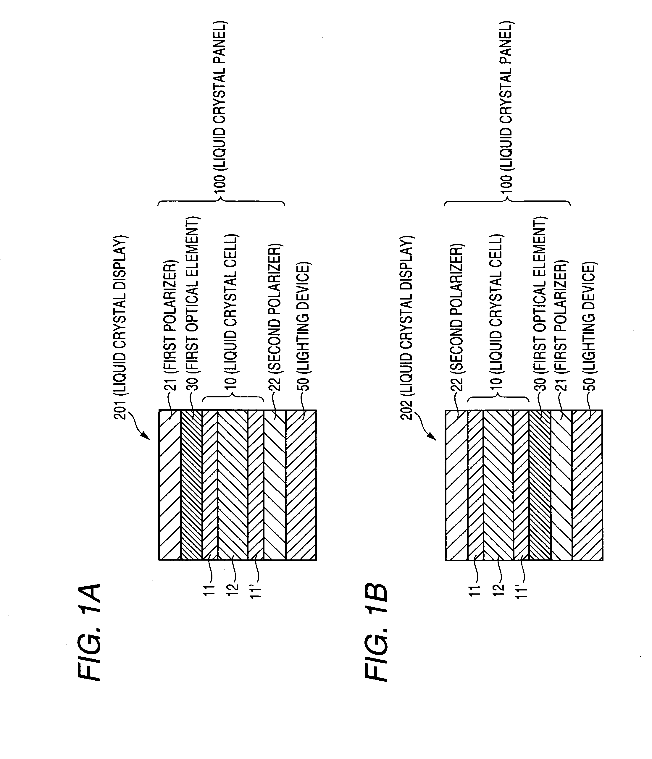
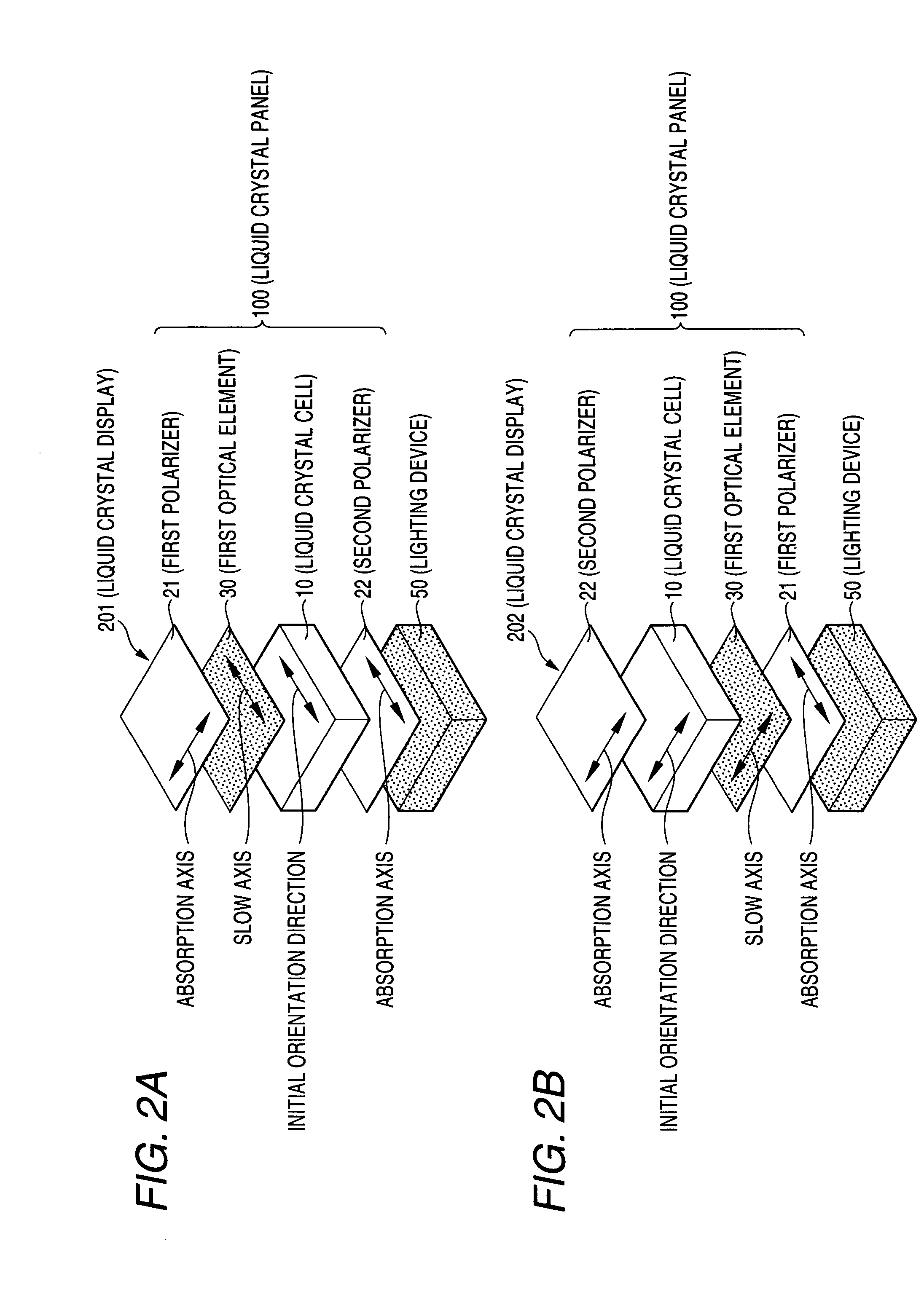
Liquid crystal display
a liquid crystal display and liquid crystal technology, applied in non-linear optics, instruments, optics, etc., can solve the problems of unsatisfactory effects of color shift, inability to operate at high temperatures and very low temperatures, and change in display properties, etc., to reduce the effect of color shift, clearer image, and reduced color shi
- Summary
- Abstract
- Description
- Claims
- Application Information
AI Technical Summary
Benefits of technology
Problems solved by technology
Method used
Image

Examples
reference example 1
[0244]A polymer film “9P75R” (trade name, thickness of 75 μm, average degree of polymerization of 2,400, degree of saponification of 99.9 mol %, manufactured by Kuraray Co., Ltd.) containing polyvinyl alcohol as a main component was uniaxially stretched 2.5 times using a roll stretching machine while the polymer film was colored in a coloring bath maintained at 30±3° C. and containing iodine and potassium iodide. Then, the polymer film was uniaxially stretched to a 6 times length of the original length of the polymer film in an aqueous solution maintained at 60±3° C. and containing boric acid and potassium iodide while a crosslinking reaction was performed. The obtained film was dried in an air circulating thermostatic oven at 50±1° C. for 30 min, to thereby obtain polarizers P1 and P2. Optical characteristics of the polarizers P1 and P2 are as shown in Table 1.
[0245]
TABLE 1Reference ExamplePolarizerP1, P2Moisture content (%)26Thickness (μm)28Single transmittance (%)44.1Parallel tra...
reference example 2
[0246]A shrinkable film A having a thickness of 60 μm (a biaxially stretched film containing polypropylene “TORAYFAN BO2874” (trade name, manufactured by Toray Industries, Inc.) was attached to each side of a polymer film having a thickness of 100 μm containing a resin obtained through hydrogenation of a ring-opened polymer of a norbornene-based monomer (norbornene-based resin) “ZEONOR ZF14-100” (trade name, average refractive index of 1.53, Tg of 136° C., Re[550] of 3.0 nm, Rth[550] of 5.0 nm, manufactured by Optes Inc.) through an acrylic pressure sensitive adhesive layer (thickness of 15 μm). Then, the resultant was stretched 1.38 times in an air-circulating thermostatic oven at 146° C. using a roll stretching machine while a machine direction of the film was held, and thereafter, the shrinkable film A was peeled off together with the acrylic pressure sensitive adhesive layer, to thereby produce a retardation film. The retardation film is referred to as retardation film 1-A, whos...
reference example 3
[0247]The shrinkable film A having a thickness of 60 μm was attached to each side of a polymer film having a thickness of 130 μm containing a resin obtained through hydrogenation of a ring-opened polymer of a norbornene-based monomer (norbornene-based resin) “ARTON FLZU 130D0” (trade name, weight average molecular weight of 78,200, average refractive index of 1.52, Tg of 135° C., Re[550] of 3.0 nm, Rth[550] of 5.0 nm, manufactured by JSR corporation) through an acrylic pressure sensitive adhesive layer (thickness of 15 μm). Then, the resultant was stretched 1.42 times in an air-circulating thermostatic oven at 146° C. using a roll stretching machine while a machine direction of the film was held, and thereafter, the shrinkable film A was peeled off together with the acrylic pressure sensitive adhesive layer, to thereby produce a retardation film. The retardation film is referred to as retardation film 1-B, whose characteristics are shown in Table 2. The retardation film showed that ...
PUM
| Property | Measurement | Unit |
|---|---|---|
| wavelength range | aaaaa | aaaaa |
| wavelength range | aaaaa | aaaaa |
| pre-tilt angle | aaaaa | aaaaa |
Abstract
Description
Claims
Application Information