
Image processing apparatus and method, photographing system, controlling method for the system, and computer-readable memory

a technology of image processing and control method, applied in the field of image processing photographing system and control method, computer-readable memory, etc., can solve the problems of cumbersome operation and pose the same problem as for film, and achieve the effect of efficient photographing and any increase in x-ray dos

Inactive Publication Date: 2009-07-07
CANON KK
View PDF16 Cites 4 Cited by
  • Summary
  • Abstract
  • Description
  • Claims
  • Application Information

AI Technical Summary

Benefits of technology

[0010]The present invention has been made in consideration of the above situation, and has as its object to provide an image processing system and a control method for the system, a photographing system and a control method for the system, and a computer-readable memory, which can efficiently photograph without any increase in X-ray dose for a person to be examined.
[0015]It is another object of the present invention to make it possible to output an image while selecting an appropriate output size from a plurality of predetermined output sizes in accordance with the to-be-output portion of the image to be output, and appropriately output the image to an existing medium or viewer without damaging the information.

Problems solved by technology

Additionally, the operation becomes cumbersome because, e.g., the direction of the X-ray detection apparatus need be changed from portrait to landscape.
Hence, even when an image is to be output to a medium other than a film, the same problem as for a film is posed.

Method used


Image

  • Image processing apparatus and method, photographing system, controlling method for the system, and computer-readable memory
  • Image processing apparatus and method, photographing system, controlling method for the system, and computer-readable memory
  • Image processing apparatus and method, photographing system, controlling method for the system, and computer-readable memory

Examples


first embodiment

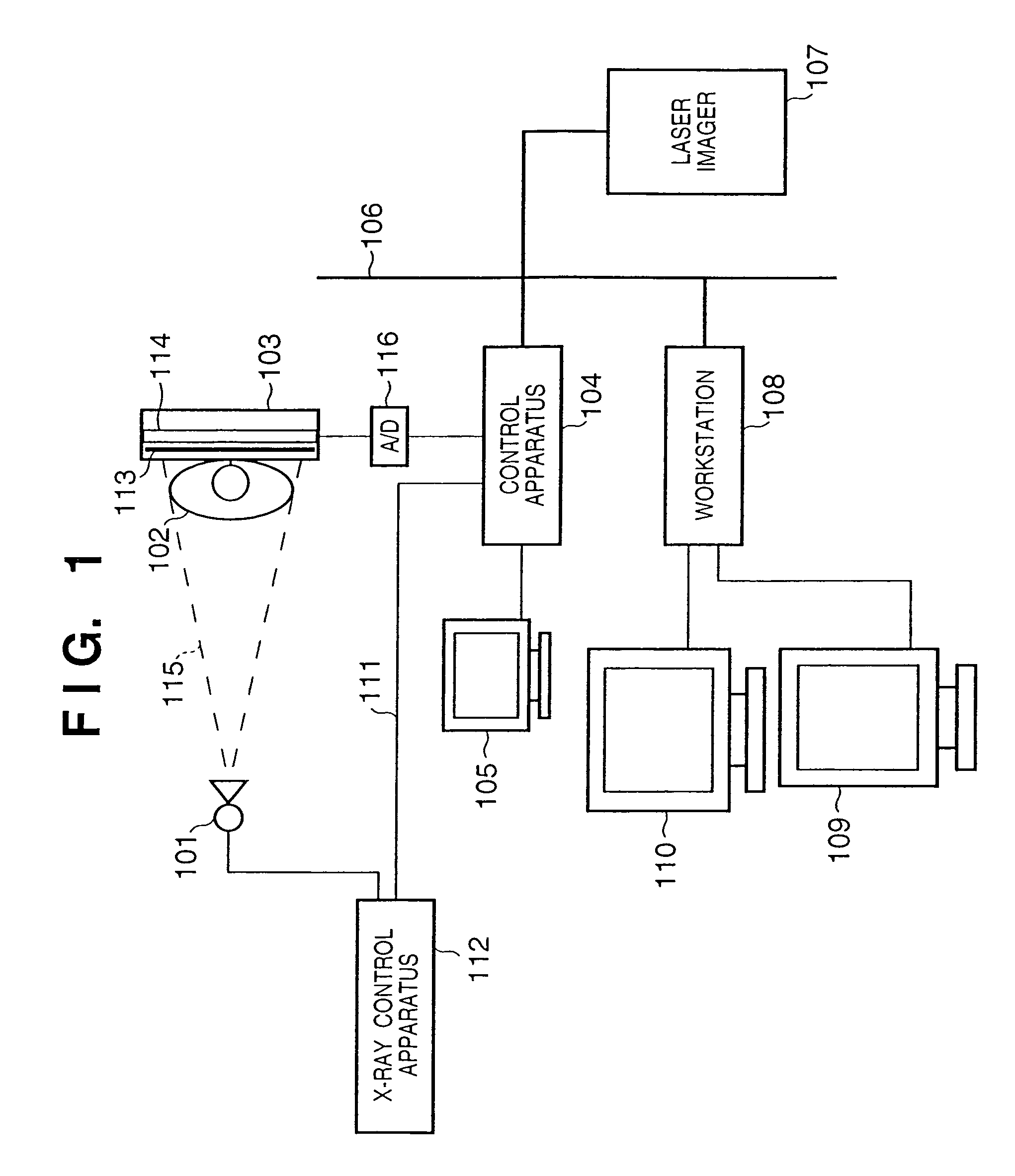
[0054]FIG. 1 is a view showing the schematic arrangement of a digital X-ray photographing system according to the first embodiment of the present invention.

[0055]Referring to FIG. 1, an X-ray source 101 generates X-rays. An X-ray control apparatus 112 controls the tube voltage or tube current of a radiation tube for generating ray. X-rays 115 generated by the X-ray source 101 pass through a person 102 to be examined as a diagnosis object and enter an X-ray detection apparatus 103. At this time, the X-rays 115 pass through the person 102 to be examined and become incident on a phosphor 113 for converting the X-rays 115 into visible light. The X-rays 115 that have passed through the person 102 to be examined contain image information with different transmission amounts according to the sizes or shapes of bones and viscera or the presence / absence of a morbid portion in the person 102 to be examined. The X-rays 115 are converted into visible light by the phosphor 113 and enter an X-ray ...

second embodiment

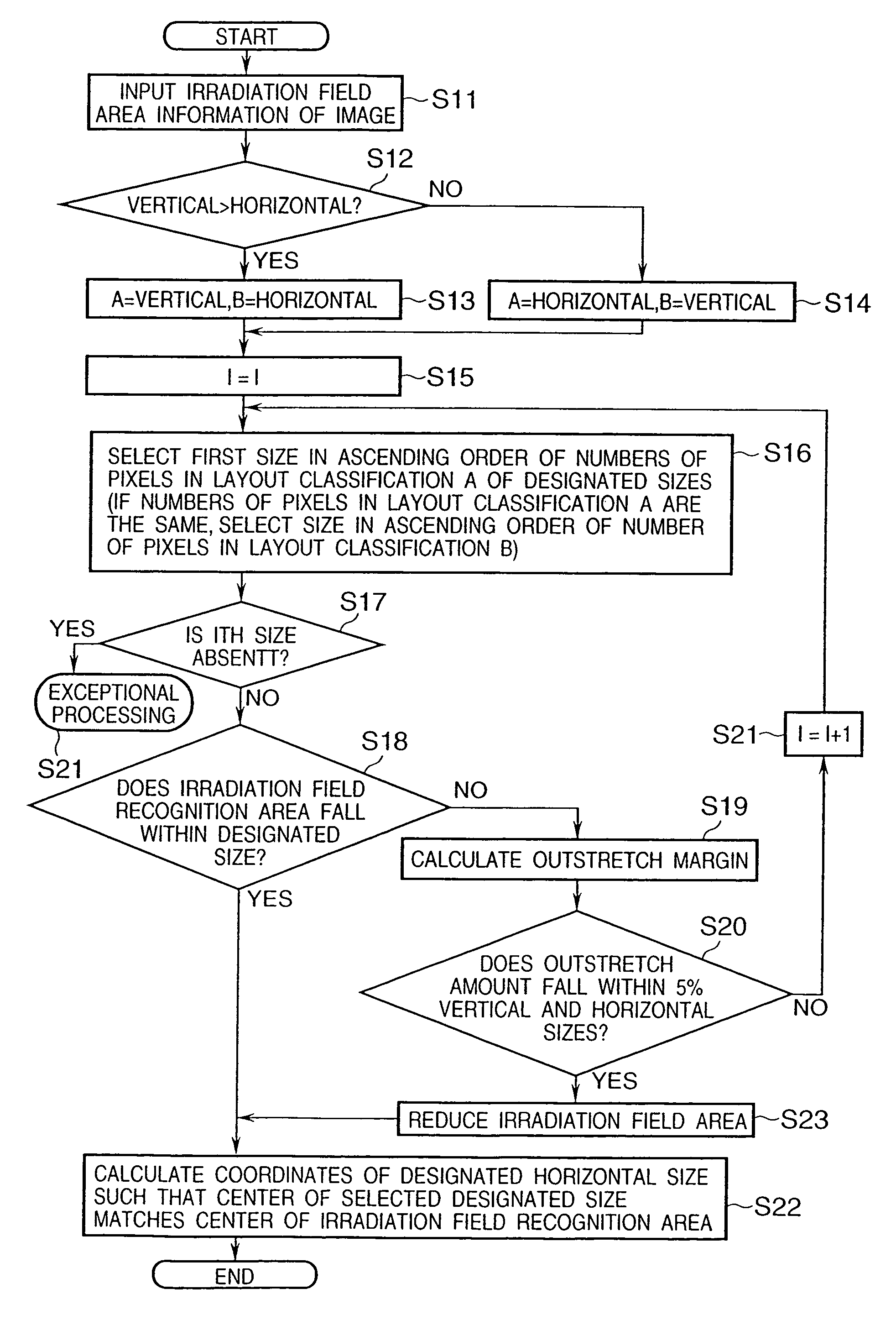
[0077]In the first embodiment, the observation area setting information is set by the observation area setting section 302 using the X-ray irradiation stop information obtained from the X-ray control apparatus 112. However, this is not always necessary. For example, as shown in FIG. 15, on the basis of digital image data acquired by an image input section 801, an irradiation field recognition section 802 automatically acquires an area where an X-ray detection apparatus 103 is irradiated with X-rays, and determines the area as an observation area. The processing described in the first embodiment is executed for this observation area. As the irradiation field recognition section 802, for example, a method disclosed in Japanese Patent Application No. 10-243020 proposed by the present applicant can be applied.

[0078]The image input section 801, an image processing section 804, output mode input section 807, output medium size input section 803, output determination section 805, and image...

third embodiment

[0080]In the first embodiment, the observation area setting information is set by the observation area setting section 302 using the X-ray irradiation stop information obtained from the X-ray control apparatus 112. However, this is not always necessary. For example, as shown in FIG. 18, observation area setting information may be obtained by setting portion information input from a to-be-photographed portion input section 1006. An observation area extraction section 1002 automatically extracts the basic observation area for the doctor from that portion. An observation area is set on the basis of the basic observation area, thereby obtaining the observation area setting information. FIGS. 16 and 17 show this example. FIG. 16 shows the front image of a chest. FIG. 17 shows the side image of the chest. In both cases, an area (an area indicated by a thin dotted line) including the area of lungs is the basic observation area for the doctor. This basic observation area is extracted by the...


PUM


Abstract

This invention has as its object to provide an image processing system and a control method for the system, a photographing system and a control method for the system, and a computer-readable memory, which can efficiently photograph without any increase in X-ray dose for a person to be examined. To achieve this object, an output mode input section inputs an output mode representing the output format of an observation area as a to-be-output area in an image to an output medium. An output medium size input section inputs the size of the effective image area of the output medium. The output determination section determines the output method of the observation area on the basis of the observation area and contents input by the input sections.

Description

[0001]This application is a divisional of application Ser. No. 09 / 408,447, filed Sep. 29, 1999, the contents of which are incorporated by reference herein.BACKGROUND OF THE INVENTION[0002]1. Field of the Invention[0003]The present invention relates to an image processing system and a control method for the system, a photographing system and a control method for the system, and a computer-readable memory, which process an image signal obtained by electronically converting an image input and output the processed signal.[0004]2. Description of the Related Art[0005]In a conventional scheme used to obtain a medical X-ray radiographic image for a long time, the distribution of X-rays transmitted through a human body is converted into a fluorescence distribution of a phosphor, the light intensity is directly printed on a film, and the film is developed. In recent years, a radiographic image is read out as an electrical signal using a scheme of forming a latent image of an X-ray intensity d...

Claims


Application Information

Patent Timeline
Patent Type & Authority Patents(United States)
IPC IPC(8): G06K9/00G06K9/32H04N1/10H04N1/393
CPCA61B6/00A61B6/4216G06T3/40A61B6/588A61B6/469
Inventor SAKO, TSUKASAOSHINO, TAKAHIRO
Owner CANON KK
Learn More