Shield tunneling machine and method capable of achieving cutter abrasion image detection

A technology of tool wear and image detection, which is applied in the field of shield machines, can solve the problems of limited air tightness of installation, increase of unstable factors, and inability to stop the machine, so as to ensure the sealing effect, reduce the detection time, and ensure the sealing. Effect

Pending Publication Date: 2021-07-30
SHANDONG UNIV
View PDF9 Cites 3 Cited by
  • Summary
  • Abstract
  • Description
  • Claims
  • Application Information

AI Technical Summary

Problems solved by technology

[0004] In a technical solution for shield machine tool detection through 3D image modeling and comparison that the inventor has learned, in order to meet the sealing requirements of the soil tank and not affect the normal operation of the shield soil tank, each inspection requires Installing the detection device on site will waste a lot of time and the airtightness of the installation is limited by the proficiency of the current operator. After the detection is completed, the detection device must be removed manually
[0005] At the same time, the tool shooting process requires the cooperation of the rotation of the cutter head to shoot different tools, and it is impossible to completely stop the machine. The rotation of the cutter head will easily cause changes in water pressure and earth pressure, and the detection process will increase instability.

Method used


Image

  • Shield tunneling machine and method capable of achieving cutter abrasion image detection
  • Shield tunneling machine and method capable of achieving cutter abrasion image detection
  • Shield tunneling machine and method capable of achieving cutter abrasion image detection

Examples


Embodiment 1

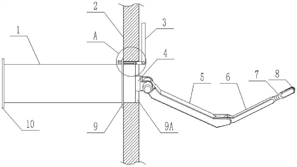
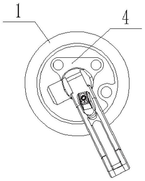
[0036] like Figure 1-Figure 3 As shown, this embodiment provides a shield machine capable of image detection of tool wear, including soil cabins, front shields, middle shields, and tail shields arranged in sequence from front to back, and a compartment is arranged between the soil cabin and the front shield Plate 2, compartment plate 2 is provided with an opening 9A, and the opening 9A is provided with a sealing plate 3 capable of automatic opening and closing, and a storage tube 1 is fixed on the side of the compartment plate 2 away from the soil cabin, and one end of the storage tube 1 is open It is set and inserted into the opening 9A, and the other end is detachably installed with an end plate 10 . The storage tube 1 is fixedly connected with the compartment plate 2 through an externally welded mounting plate 9 .

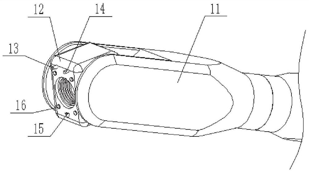
[0037] A binocular camera 8 and a drive assembly are set in the storage tube 1, and the drive assembly can drive the binocular camera 8 to extend into or retr...

Embodiment 2

[0053] This embodiment provides a tool wear detection method in a shield soil chamber, which is used for the tool wear detection of the shield machine capable of realizing tool wear image detection described in Embodiment 1, including the following steps:

[0054] Before the excavation of the shield machine, the sealing plate 3 is opened to connect the soil cabin and the storage tube 1, the driving component drives the binocular camera 8 into the shield soil cabin, and the binocular camera 8 is aimed at different tools in sequence to shoot, and the host computer according to the obtained image information Complete the 3D modeling program. The 3D model includes the spatial coordinate system at the end of the detection device and the morphological model of the cutter head and cutter. After the initial model of the shield cutter is built, the binocular camera 8 and the drive assembly are retracted, and then the sealing plate 3 is closed;

[0055] When the tool needs to be detected...


PUM


Abstract

The invention relates to a shield tunneling machine and method capable of achieving cutter abrasion image detection. The shield tunneling machine comprises a soil bin, a front shield, a middle shield and a tail shield which are sequentially arranged from front to back, wherein a bin partition plate is arranged between the soil bin and the front shield, an opening is formed in the bin partition plate, a sealing plate capable of being automatically opened and closed is arranged at the opening, a storage barrel is fixed to the side, away from the soil bin, of the bin partition plate, one end of the storage barrel is open and inserted into the opening, an end plate is detachably mounted at the other end of the storage barrel, a binocular camera and a driving assembly are arranged in the storage barrel, the driving assembly can drive the binocular camera to extend into or retract into the soil bin from the storage barrel, the binocular camera can complete camera shooting of a cutter in the soil bin and transmit the image to an upper computer, and the upper computer can complete three-dimensional modeling of the cutter according to image information of the binocular camera and judge the abrasion degree of the cutter. According to the invention, imaging detection of the cutter in the soil bin of the shield tunneling machine can be completed, and the efficiency and accuracy of cutter wear detection are improved.

Description

technical field [0001] The disclosure belongs to the technical field of geotechnical engineering, and in particular relates to a shield machine and a method capable of realizing tool wear image detection. Background technique [0002] The statements herein merely provide background information related to the present disclosure and do not necessarily constitute prior art. [0003] Shield machine knives need to be replaced in time after wear or failure, otherwise it will lead to excessive wear, breakage, displacement of the knives, abnormal damage to the bearings and even severe wear of the cutter head, which will greatly reduce the tunneling efficiency. Among the existing tool wear detection methods, the method of opening the cabin and directly inspecting it by divers is the most effective, but under the action of earth pressure and water pressure in the formation, there is a great safety risk in opening the cabin of the shield machine. [0004] In a technical solution for s...

Claims


Application Information

Patent Timeline
Patent Type & Authority Applications(China)
IPC IPC(8): G01N21/01G01N21/15G01N21/84
CPCG01N21/01G01N21/15G01N21/84G01N2021/0112
Inventor 刘洪亮张延欢李利平李术才王旌周宗青孙子正杨光宇刘洋冀笑瑀
Owner SHANDONG UNIV
Why Eureka
Try Eureka