System and method to automate placement of RFID repeaters

a repeater and automatic technology, applied in the field of electrical communication, can solve the problems of dead spots, rfid technology failed as tracking and inventory method, and passive rfid technology for inventory tracking

Inactive Publication Date: 2009-07-14
INT BUSINESS MASCH CORP
View PDF8 Cites 54 Cited by
  • Summary
  • Abstract
  • Description
  • Claims
  • Application Information

AI Technical Summary

Problems solved by technology

A problem in the implementation of passive RFID technology for inventory tracking arises from dead spots.
Dead spots can be caused by dense packing of passive RFID tags where inventory materials shield the tags and interrupt signal transmission.
Even if the RFID transceiver successfully reads fifty of the sixty RFID tags located on the pallet, the RFID technology failed as a tracking and inventory method because the RFID technology gathered incomplete and inaccurate information.

Method used


Image

  • System and method to automate placement of RFID repeaters
  • System and method to automate placement of RFID repeaters
  • System and method to automate placement of RFID repeaters

Examples


Embodiment Construction

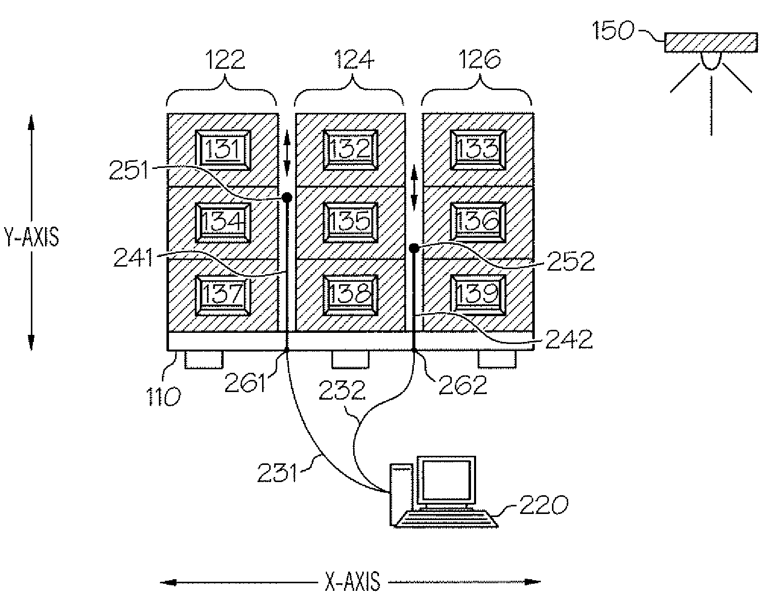
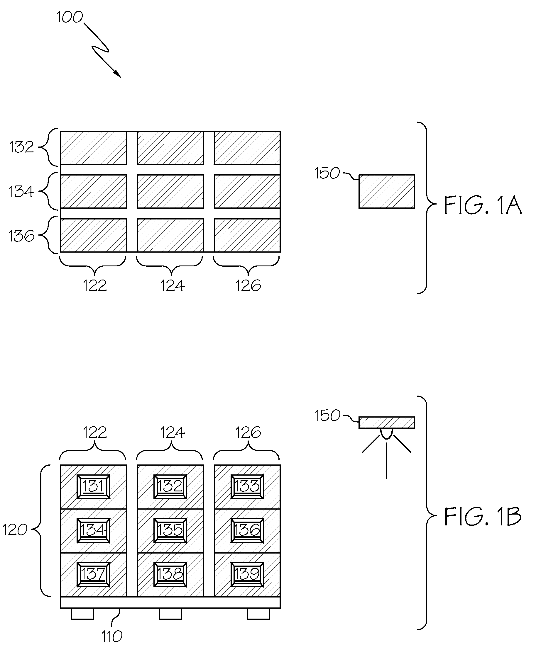
[0015]FIG. 1A and FIG. 1B show product pallet 100 representing a densely packed pallet of goods with RFID tags. Product pallet 100 comprises pallet 110 and a plurality of packages 120 in a generally cubical arrangement on the pallet. From the front view (FIG. 1B), plurality of packages 120 are shown stacked vertically (y axis) in first package column 122, second package column 124, and third package column 126. From the top view (FIG. 1A), it is also shown that the first, second and third package columns are also three packages deep (z axis) as well as three packages high (y axis). Accordingly, the plurality of packages can also be described as stacked in fourth package column 132, fifth package column 134, and sixth package column 136 that are each three packages wide (x axis) as well as three packages high (y axis). RFID transceiver 150 locates at a position within transmission range of product pallet 100.

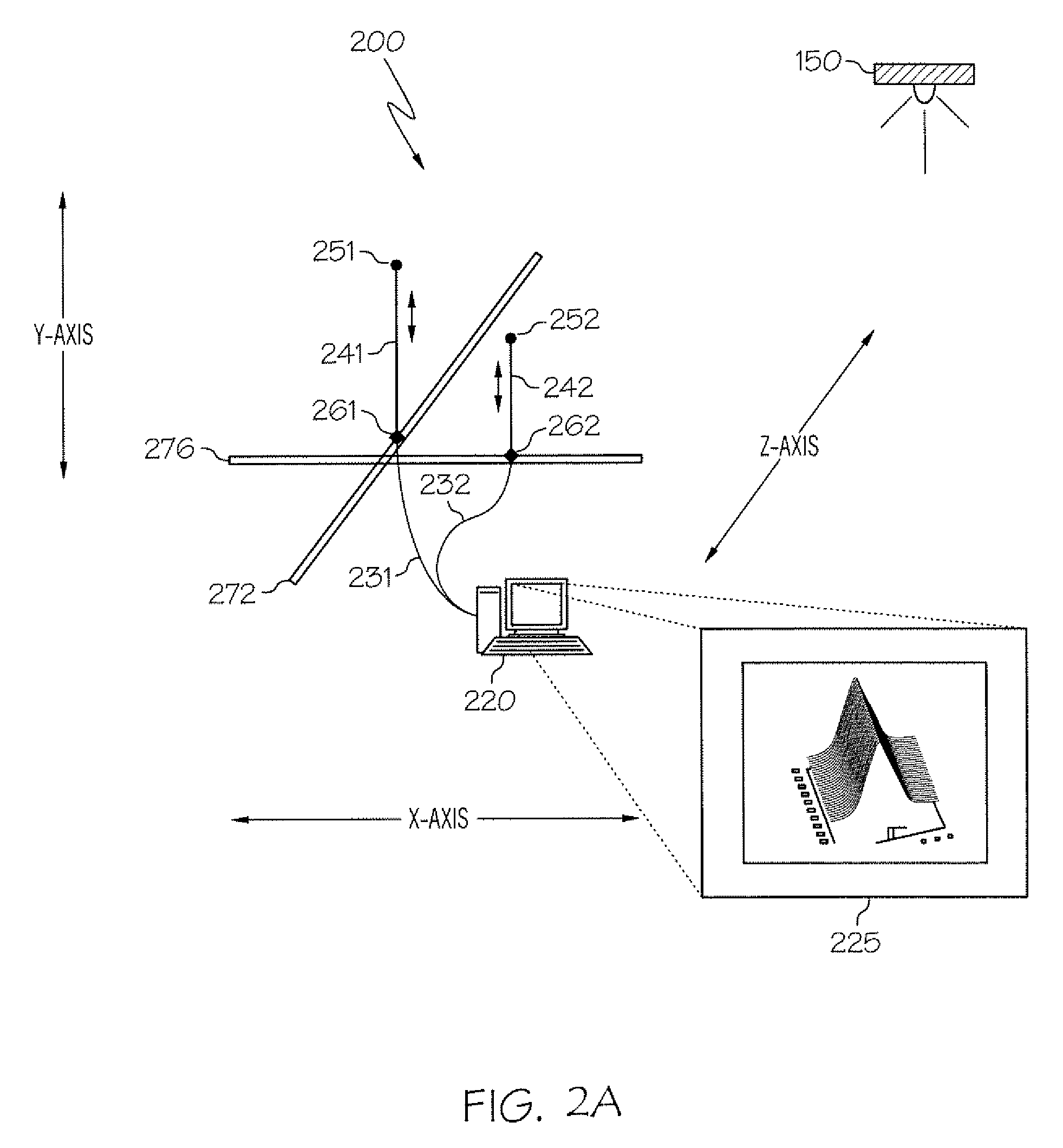
[0016]FIG. 2 shows automatic RFID tuner 200 in simplified form with first RF...


PUM


Abstract

The Automatic RFID Tuner has one or more RFID repeaters that can travel in the x, y and z axes through a densely packed pallet of goods. The RFID repeater identifies dead spots where RF signals from an RFID transceiver do not penetrate the dense packaging. The RFID repeater calculates a position that ensures the RF signal will reach all passive RFID tags in the dense packaging. The RFID repeater moves to the calculated position so that the RFID transceiver's signal will read all passive RFID tags in the dense packaging.

Description

FIELD OF THE INVENTION[0001]The invention relates generally to the field of electrical communications and relates specifically to querying an information containing device for an immediate reply.BACKGROUND OF THE INVENTION[0002]Radio Frequency Identification (“RFID”) technology comprises two elements: a transponder (hereafter “tag”), which is generally a small, paper thin computer chip with an antenna which stores data, and a transceiver which utilizes a radio signal in the approximate 800-930 Mhz UHF range to read the data from the tag. Active RFID tags contain a power source, such as a battery, and can actively transmit the tag's stored data. Passive RFID tags cannot transmit by themselves, and require a RFID transceiver to provide power via radio signals transmitted by the RFID transceiver. As passive RFID tags pass by a RFID transceiver, the transceiver powers the tag and reads the data stored on the tag.[0003]Large retail companies, such as WAL-MART®, find passive RFID tags adv...

Claims


Application Information

Patent Timeline
Patent Type & Authority Patents(United States)
IPC IPC(8): G08B13/14
CPCG06K7/10178G06K7/0008
Inventor BHOGAL, KULVIR S.BOSS, GREGORY J.HAMILTON, II, RICK A.POLOZOFF, ALEXANDREWATERS, TIMOTHY M.
Owner INT BUSINESS MASCH CORP
Why Eureka
Try Eureka