Multiple display monitor

a multi-display monitor and monitor technology, applied in the field of computers, can solve the problems of user discomfort, difficulty in visually scanning from one monitor to another, and the cost of the monitor itself, and achieve the effect of preventing neck strain and less production cost of producing a multiple-display monitor

Inactive Publication Date: 2009-07-14
MICROSOFT TECH LICENSING LLC
View PDF24 Cites 42 Cited by
  • Summary
  • Abstract
  • Description
  • Claims
  • Application Information

AI Technical Summary

Benefits of technology

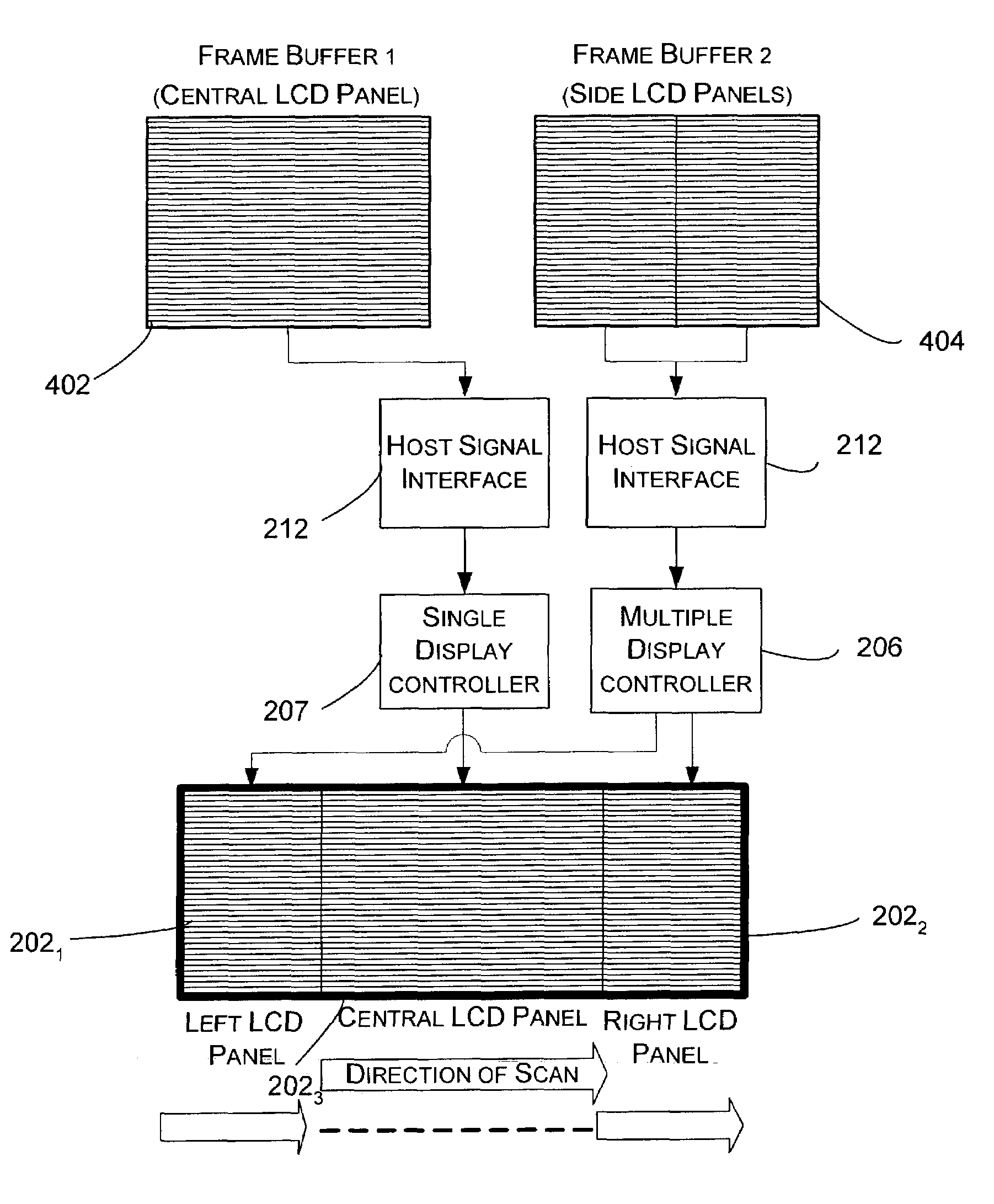
[0008]There are a number of advantages provided by the monitor of the present invention. First, the side panels or displays may be located immediately adjacent to the central work area display. This arrangement prevents neck strain, because a user does not have to turn his or her head that much to view the side monitors or displays. In addition, the field of view between the adjacent panels is not interrupted such as in the case where two separate monitors are used. Moreover, because the two side panels are smaller than a single display of the same size, the production cost of producing a multiple display monitor is less.
[0009]Narrow seams between the side panels and the central work area display provide a smooth transition between the displays. In addition, the three part visual screen provides a natural division into a larger central work area (i.e., the central work area display) and peripheral areas (i.e., the side displays) that may be used for notifications, tree views, tool bars, and other items.

Problems solved by technology

Because of the cost of producing large displays, purchasing two displays may provide the same amount of desktop space for less price than a large, single monitor.
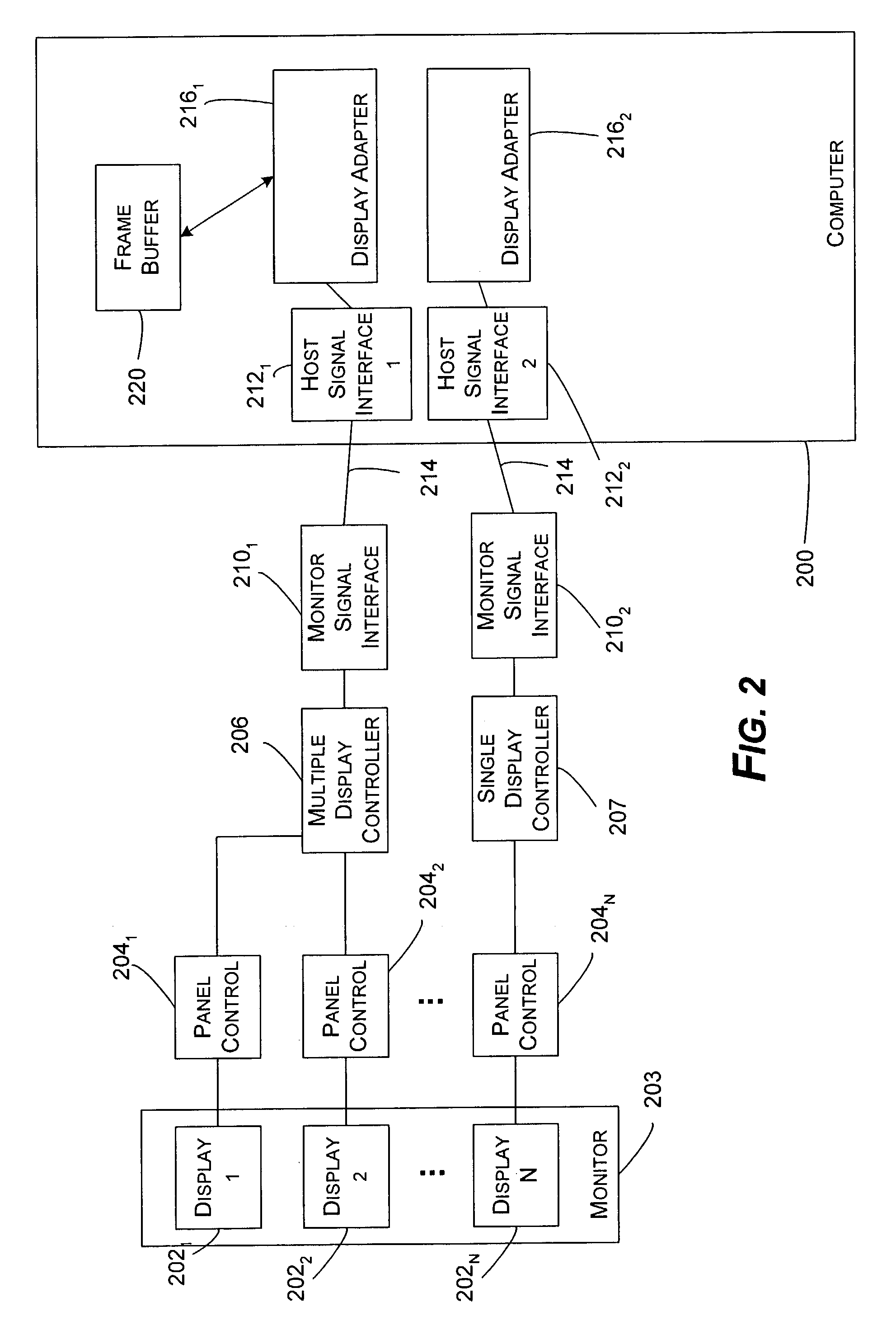
In addition to the cost of the monitor itself, however, conventional multiple monitor systems require an additional cable and display adapter, usually in the form of a video card, for each monitor.
A drawback to the use of multiple monitors is that visually scanning from one monitor to another may be difficult.
In addition, the use of multiple monitors may cause discomfort for a user when viewing from one display to another.

Method used


Image

  • Multiple display monitor
  • Multiple display monitor
  • Multiple display monitor

Examples


Embodiment Construction

Exemplary Operating Environment

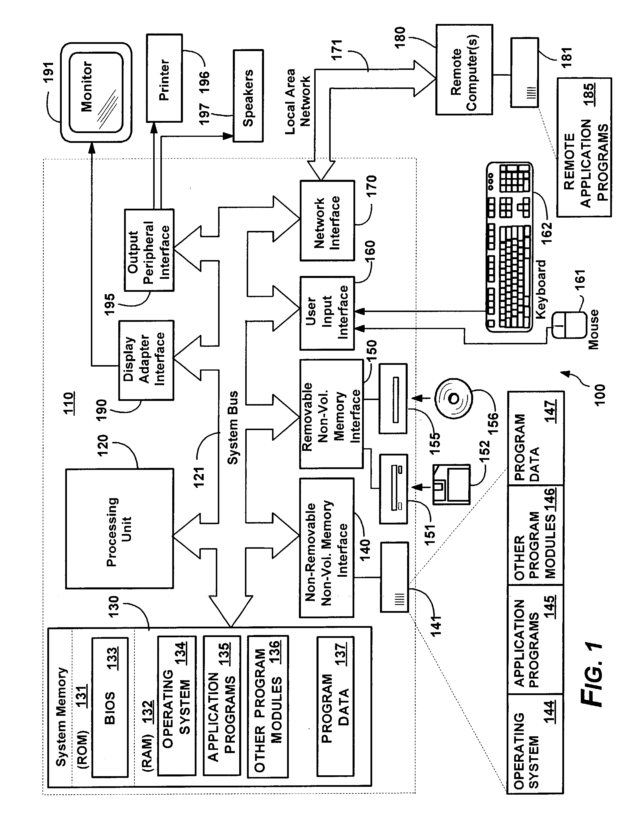
[0024]FIG. 1 illustrates an example of a suitable computing system environment 110 on which the invention may be implemented. The computing system environment 110 is only one example of a suitable computing environment and is not intended to suggest any limitation as to the scope of use or functionality of the invention. Neither should the computing environment 110 be interpreted as having any dependency or requirement relating to any one or combination of components illustrated in the exemplary operating environment 110.

[0025]The invention is operational with numerous other general purpose or special purpose computing system environments or configurations. Examples of well known computing systems, environments, and / or configurations that may be suitable for use with the invention include, but are not limited to, personal computers, server computers, hand-held or laptop devices, multiprocessor systems, microcontroller-based systems, set top boxes, prog...


PUM


Abstract

A monitor having multiple displays within the same housing. The displays may be, for example, separate LCD panels that are placed in close proximity to one another so as to give the appearance of a single, large display. At least two of the displays may be treated by a computer connected to the monitor as a single display. A display controller divides a single frame of information that is provided by a display adapter of the computer into display information for multiple displays. By using the multiple display controller, the multiple display monitor may have more displays or panels than the number of cables linking the monitor to a computer. The special display controller also does not require a graphics card for each display. A three panel or display monitor is provided in which a central, centered work area display is framed by two side panels or displays.

Description

TECHNICAL FIELD OF THE INVENTION[0001]The present invention is generally directed to computers, and more specifically directed to the use of multiple displays with a single computer.BACKGROUND OF THE INVENTION[0002]The use of multiple displays by computer enthusiasts continues to grow. Using more than one display allows a user to stretch his or her desktop to show more programs than if a single display is used. In addition, a single program may be stretched over multiple displays so that more of a document, such as a spreadsheet, may be seen without scrolling. A presentation may also have several pages open, with the pages spread across several different displays.[0003]Because of the cost of producing large displays, purchasing two displays may provide the same amount of desktop space for less price than a large, single monitor. In addition to the cost of the monitor itself, however, conventional multiple monitor systems require an additional cable and display adapter, usually in th...

Claims


Application Information

Patent Timeline
Patent Type & Authority Patents(United States)
IPC IPC(8): G09G5/00G06F15/167G06T1/60G09G5/36G09G5/39G06F1/16G06F3/14
CPCG06F1/1601G06F1/1616G06F1/1641G06F3/1431G09G2340/0492G06F3/1438G09G2310/0283
Inventor WESTERINEN, WILLIAM J.POWELL, III, WILLIAM CHAMBERS
Owner MICROSOFT TECH LICENSING LLC
Why Eureka
Try Eureka