Zoom lens system and image pickup apparatus including the same
a technology of zoom lens and image pickup, which is applied in the field of zoom lens system, can solve the problems of difficult to compensate for such aberrations in a good manner, the simple increase of the refractive power of the lens group, and the long total length of the zoom lens system. , to achieve the effect of high optical performance, simple lens configuration, and high zoom ratio
- Summary
- Abstract
- Description
- Claims
- Application Information
AI Technical Summary
Benefits of technology
Problems solved by technology
Method used
Image
Examples
numerical example 1
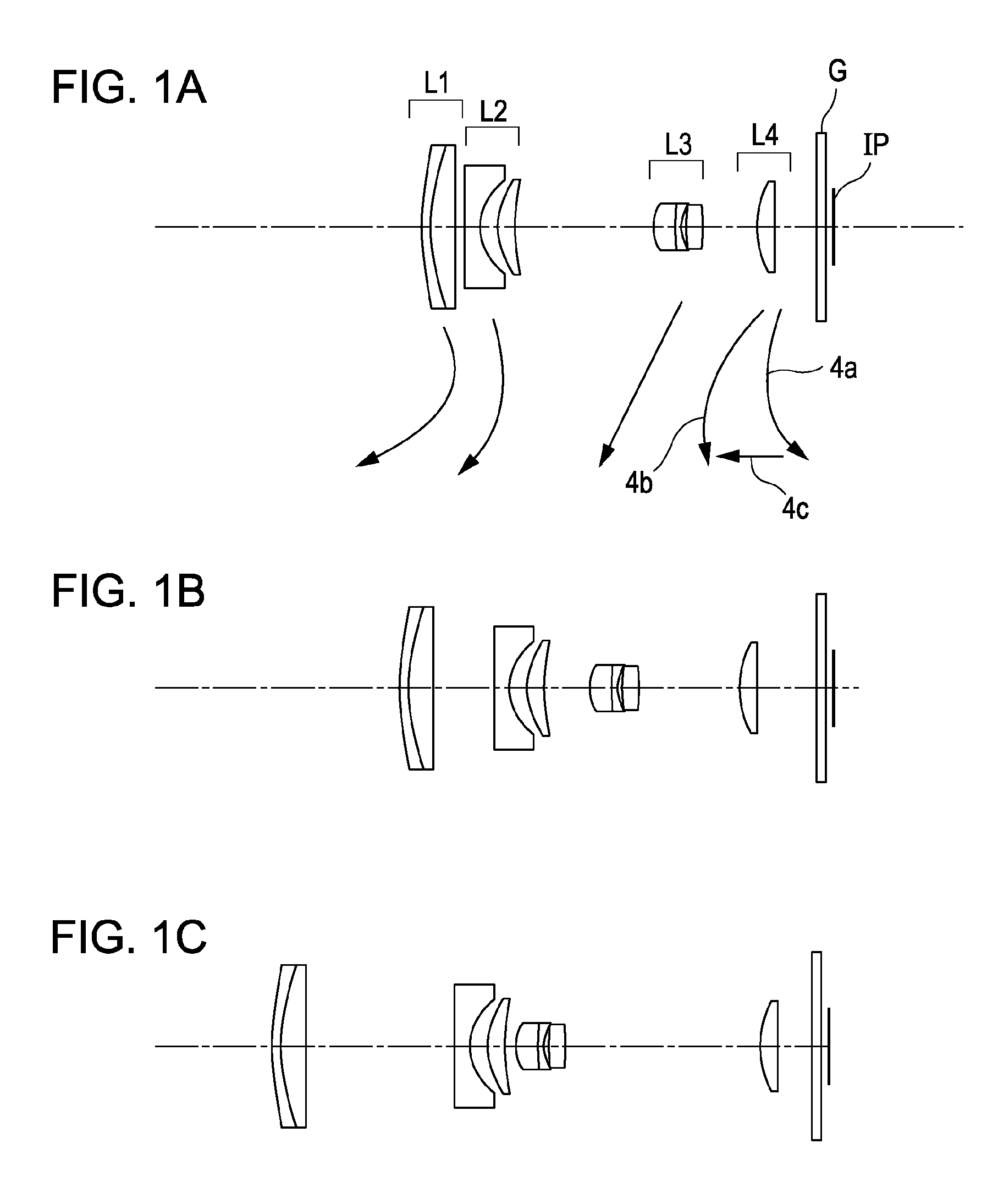
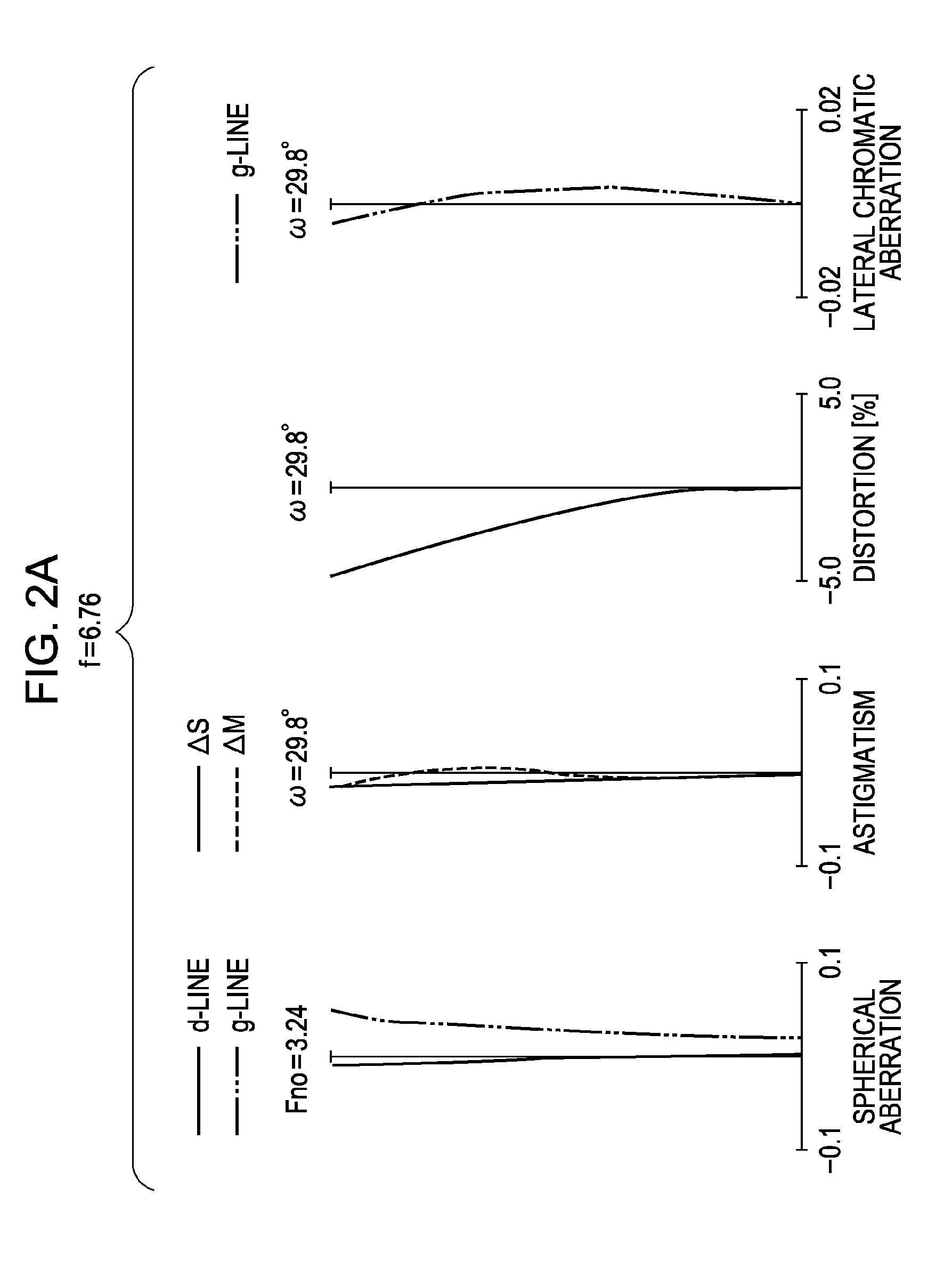
[0111]f=6.76˜32.19 Fno=3.24˜5.88 2ω=59.6˜13.6[0112]R 1=36.425 D 1=0.90 N 1=1.846660 ν 1=23.9[0113]R 2=20.870 D 2=2.60 N 2=1.804000 ν 2=46.6[0114]R 3=423.219 D 3=variable[0115]* R 4=−120.928 D 4=1.65 N 3=1.848620 ν 3=40.0[0116]* R 5=5.369 D 5=1.97[0117]R 6=9.531 D 6=1.70 N 4=1.922860 ν 4=18.9[0118]R 7=21.305 D 7=variable[0119]* R 8=5.124 D 8=2.30 N 5=1.882997 ν 5=40.8[0120]R 9=16.216 D 9=0.70 N 6=1.808095 ν 6=22.8[0121]R10=4.203 D10=0.52[0122]R11=10.171 D11=1.80 N 7=1.487490 ν 7=70.2[0123]R12=−14.353 D12=variable[0124]R13=12.341 D13=1.80 N 8=1.487490 ν 8=70.2[0125]R14=131.500 D14=variable[0126]R15=∞D15=1.00 N 9=1.516330 ν 9=64.1[0127]R16=∞[0128]\Focal Length 6.76 14.94 32.19[0129]variable Range\[0130]D 3 1.20 6.79 16.40[0131]D 7 15.09 4.97 1.17[0132]D12 5.85 11.02 21.19[0133]D14 4.69 6.23 3.85
Aspherical Coefficient[0134]4th surface: k=0.00000e+00 A=0 B=1.11274e−05[0135]C=0.00000e+00 D=0.00000e+00 E=0.00000e+00[0136]5th surface: k=−2.79279e+00 A=0 B=1.72320e−03[0137]C=−3.57723e−05 D=8...
numerical example 2
[0141]f=6.76˜32.35 Fno=3.30˜5.69 2ω=59.6˜13.6[0142]R 1=33.137 D 1=0.90 N 1=1.846660 ν 1=23.9[0143]R 2=19.192 D 2=2.80 N 2=1.804000 ν 2=46.6[0144]R 3=242.172 D 3=variable[0145]* R 4=−96.261 D 4=1.65 N 3=1.848620 ν 3=40.0[0146]* R 5=5.396 D 5=1.89[0147]R 6=9.316 D 6=1.80 N 4=1.922860 ν 4=18.9[0148]R 7=20.239 D 7=variable[0149]* R 8=5.232 D 8=2.10 N 5=1.882997 ν 5=40.8[0150]R 9=8.992 D 9=0.90 N 6=1.922860 ν 6=18.9[0151]R10=4.476 D10=0.49[0152]R11=10.995 D11=1.70 N 7=1.603112 ν 7=60.6[0153]R12=−17.967 D12=variable[0154]R13=11.887 D13=1.80 N 8=1.487490 ν 8=70.2[0155]R14=91.923 D14=variable[0156]R15=∞D15=1.00 N 9=1.516330 ν 9=64.1[0157]R16=∞[0158]\Focal Length 6.76 15.26 32.35[0159]variable Range\[0160]D 3 1.20 7.43 16.37[0161]D 7 16.47 5.78 1.68[0162]D12 7.50 12.19 20.99[0163]D14 3.91 5.67 3.96
Aspherical Coefficient[0164]4th surface: k=0.00000e+00 A=0 B=1.61717e−05[0165]C=0.00000e+00 D=0.00000e+00 E=0.00000e+00[0166]5th surface: k=−2.66336e+00 A=0 B=1.62355e−03[0167]C=−3.08981e−05 D=7.08...
numerical example 3
[0171]f=6.76˜32.35 Fno=2.93˜5.35 2ω=59.6˜13.6[0172]R 1=37.196 D 1=0.90 N 1=1.846660 ν 1=23.9[0173]R 2=21.532 D 2=2.70 N 2=1.804000 ν 2=46.6[0174]R 3=440.672 D 3=variable[0175]* R 4=−107.214 D 4=1.65 N 3=1.848620 ν 3=40.0[0176]* R 5=5.516 D 5=1.93[0177]R 6=9.693 D 6=1.80 N 4=1.922860 ν 4=18.9[0178]R 7=21.867 D 7=variable[0179]* R 8=5.118 D 8=2.30 N 5=1.882997 ν 5=40.8[0180]R 9=16.888 D 9=0.70 N 6=1.808095 ν 6=22.8[0181]R10=4.211 D10=0.52[0182]R11=10.186 D11=1.80 N 7=1.487490 ν 7=70.2[0183]R12=−14.473 D12=variable[0184]R13=14.277 D13=1.80 N 8=1.603112 ν 8=60.6[0185]R14=91.600 D14=variable[0186]R15=∞D15=0.50 N 9=1.516330 ν 9=64.1[0187]R16=∞[0188]\Focal Length 6.76 14.94 32.35[0189]Variable Range\[0190]D 3 1.20 7.61 17.46[0191]D 7 14.85 4.83 1.01[0192]D12 5.25 9.95 20.08[0193]D14 4.84 6.36 3.70
Aspherical Coefficient[0194]4th surface: k=0.00000e+00 A=0 B=6.10931e−06[0195]C=0.00000e+00 D=0.00000e+00 E=0.00000e+00[0196]5th surface: k=−2.94241e+00 A=0 B=1.67564e−03[0197]C=−3.45129e−05 D=7.5...
PUM
 Abstract
Description
Claims
Application Information
 - R&D
- Intellectual Property
- Life Sciences
- Materials
- Tech Scout
- Unparalleled Data Quality
- Higher Quality Content
- 60% Fewer Hallucinations
Browse by: Latest US Patents, China's latest patents, Technical Efficacy Thesaurus, Application Domain, Technology Topic, Popular Technical Reports.
© 2025 PatSnap. All rights reserved.Legal|Privacy policy|Modern Slavery Act Transparency Statement|Sitemap|About US| Contact US: help@patsnap.com


