Radiator core support

a technology of radiator core and support rod, which is applied in the direction of propulsion parts, transportation and packaging, light and heating apparatus, etc., can solve the problems of low rigidity, too heavy in weight, and room for improvement in rigidity and weight of conventional radiator supports, so as to improve the rigidity of the first metal frame, reduce manufacturing costs, and improve the effect of rigidity

Inactive Publication Date: 2009-07-21
CALSONIC KANSEI CORP
View PDF16 Cites 2 Cited by
  • Summary
  • Abstract
  • Description
  • Claims
  • Application Information

AI Technical Summary

Benefits of technology

[0010]Therefore, the radiator core support of the invention can strengthen rigidity and decrease weight and excessive portions of an entire radiator core support more than the conventional radiator core supports using the plastic material and the metal members, because the metal right and left fixing members fixed to the motor vehicle body are connected by the first metal frame. This also increases rigidity of the motor vehicle body, thereby improving stability and controllability of a motor vehicle. The heat exchanger can be tightly and stably supported by the first metal frame and the second metal frame. In addition, the fan motor can be tightly supported by the first metal frame, and rigidity of the first metal frame can be improved at the same time.
[0016]Therefore, the first metal frame can be built in lower weight and at low manufacturing cost, keeping higher rigidity of the radiator core support.
[0020]Therefore, the fan motor can be tightly supported by the two beams and the fan fixing member at low manufacturing costs and in lower weight, and rigidity of the first metal frame can be improved at the same time.

Problems solved by technology

The radiator core supports entirely made from the metal material ensure high rigidity at any portions thereof, but they are too heavy in weight.
The radiator core supports entirely made from the plastic material can decrease their weight, but they usually have a portion of low rigidity.
The above known conventional radiator core supports, however, encounter problems in that there is room for improvement in the rigidity and the weight of the conventional radiator supports, because the rigidity of the conventional core supports are improved by replacing only weak plastic portions thereof with metal members and / or adding the metal members to the weak plastic portions, allowing for only the weak portions in part, not entirely.
On the other hand, they have excessive thickness and / or configuration, wasting their material.

Method used


Image

  • Radiator core support
  • Radiator core support
  • Radiator core support

Examples


Embodiment Construction

[0032]Throughout the following detailed description, similar reference characters and numbers refer to similar elements in all figures of the drawings, and their descriptions are omitted for eliminating duplication.

[0033]A radiator core support of an embodiment according to the present invention will be described with reference to the accompanying drawings.

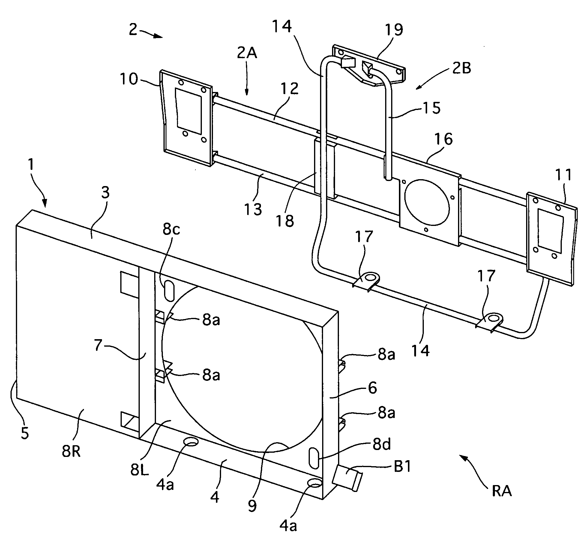
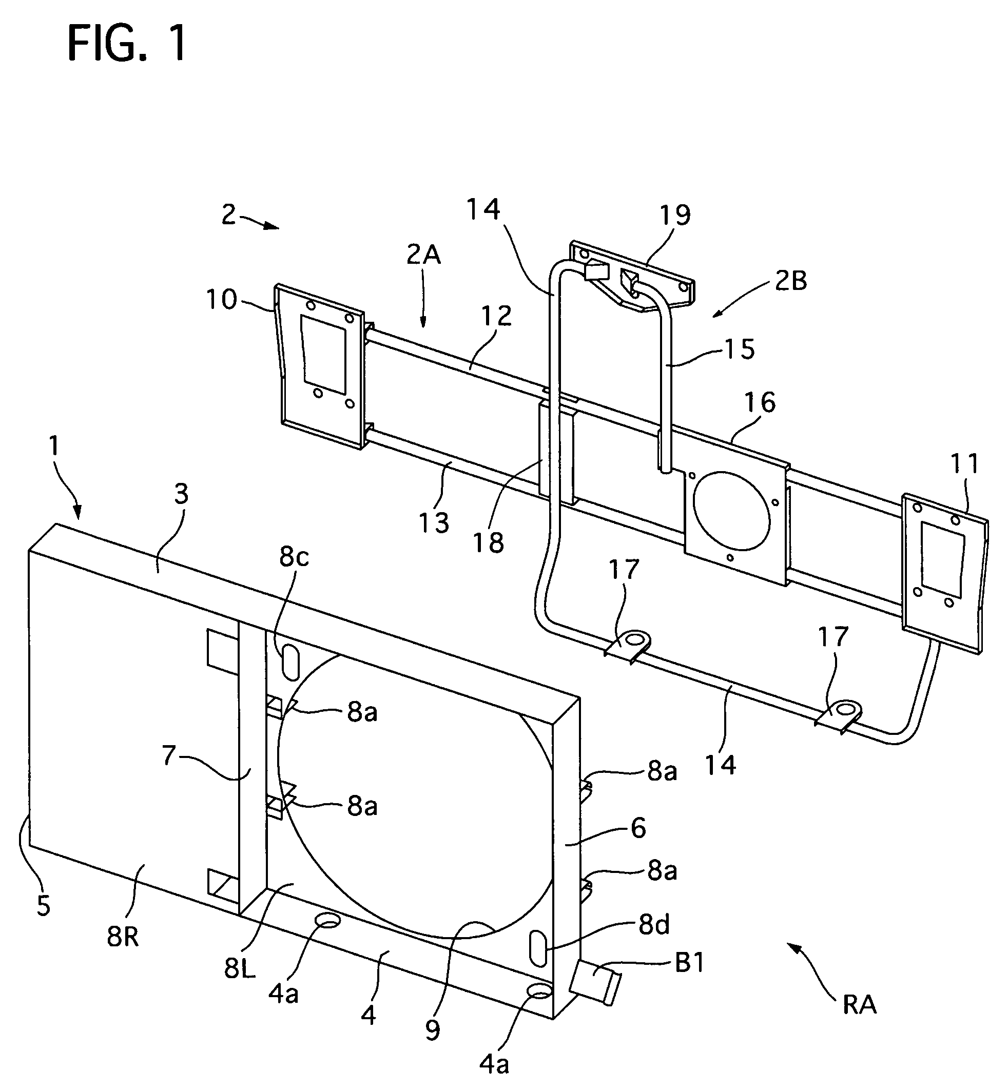
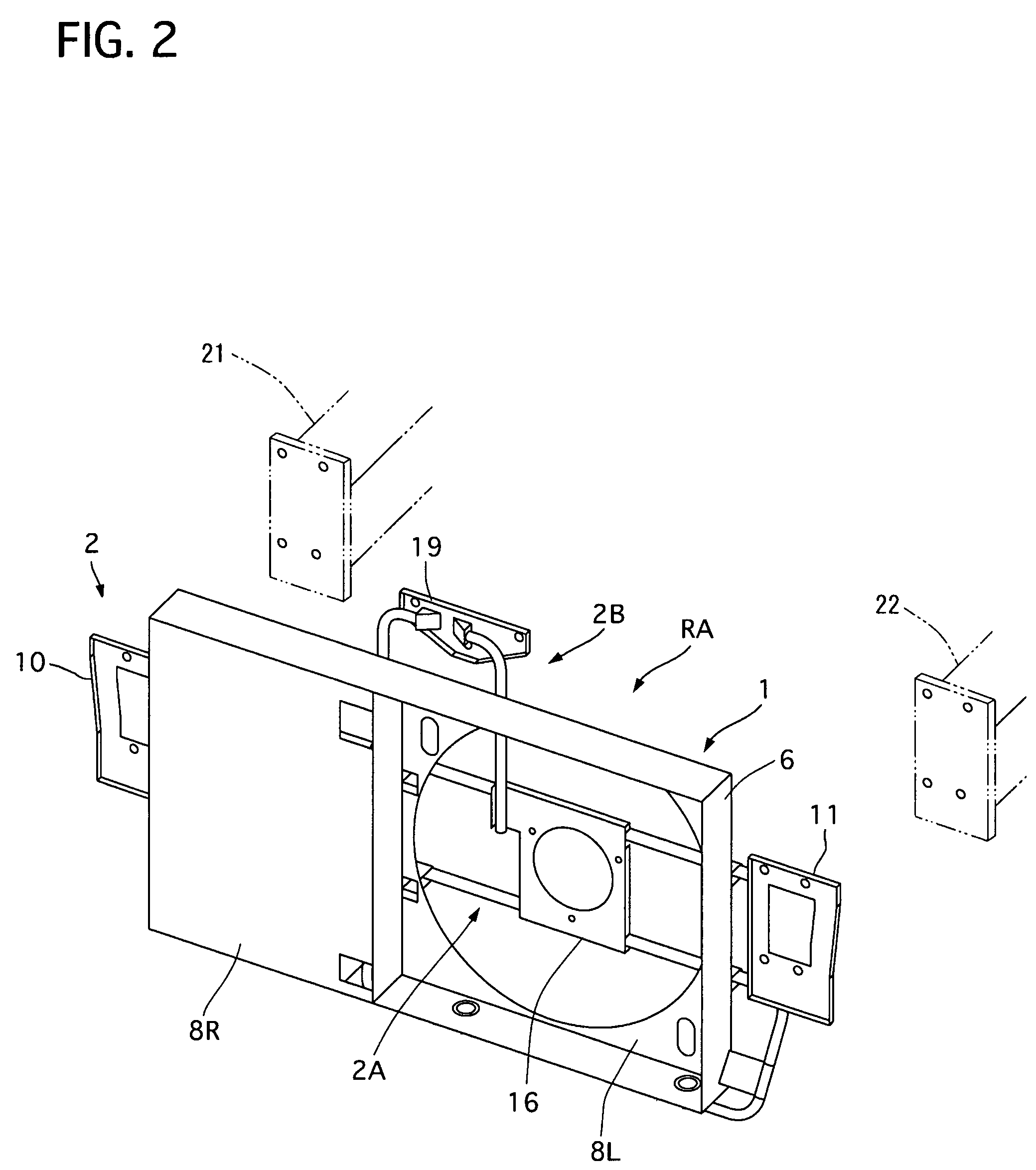
[0034]Referring to FIGS. 1 to 3 of the drawings, there is shown the radiator core support of the embodiment. Note that terms “left” and “right”, used hereinafter, respectively indicate those with respect with a motor vehicle body, not in the attached Figures.

[0035]The radiator core support RA has a radiator core support main body 1 integrally made of plastic material and a metal part 2 including a first metal frame 2A and a second metal frame 2B. The first metal frame 2A consists of an upper beam 12 and a lower beam 13, and the second metal frame 2B consists of a first beam 14 and a second beam 15.

[0036]As shown in FIGS. 1 to 4, t...


PUM


Abstract

A radiator core support includes a radiator core support main body that is made of plastic material, a right fixing member and a left fixing member that are made of metal, and a first metal frame. The right fixing member and the left fixing member are fixed on a right side member and a left side member of a motor vehicle body, respectively. The first metal frame extends in a lateral direction of the motor vehicle body so as to connect the right fixing member and the left fixing member with each other and support the radiator core support main body.

Description

BACKGROUND OF THE INVENTION[0001]1. Field of the Invention[0002]The present invention relates to a radiator core support that is made of a combination of metal members and plastic material for supporting a heat exchanger and is adapted for a motor vehicle.[0003]2. Description of the Related Art[0004]Some of conventional radiator core supports adapted for motor vehicles are constructed so that all parts of the radiator core supports are made from either one of plastic material and metal material. The radiator core supports entirely made from the metal material ensure high rigidity at any portions thereof, but they are too heavy in weight. The radiator core supports entirely made from the plastic material can decrease their weight, but they usually have a portion of low rigidity.[0005]In order to obtain radiator core supports with lighter weight and lower rigidity, conventional radiator core supports, made of a combination of metal members and plastic material, are used. Specifically,...

Claims


Application Information

Patent Timeline
Patent Type & Authority Patents(United States)
IPC IPC(8): B60K11/04
CPCB62D25/084
Inventor WATANABE, TOSHIHARUKOBAYASHI, HIDEKIARAKI, SHINJIITO, OSAMUMORI, EIICHI
Owner CALSONIC KANSEI CORP
Why Eureka
Try Eureka