Angle regulator and equipment with the angle regulator

a technology of angle regulator and angle regulator, which is applied in the direction of instruments, electrical apparatus casings/cabinets/drawers, portable computers, etc., can solve the problems of angle regulator only providing constant angle, user fatigue easily for holding the same posture, and the magnitude of the angle regulator cannot be freely changed according to different requirements of users

Inactive Publication Date: 2009-07-28
HON HAI PRECISION IND CO LTD
View PDF18 Cites 65 Cited by
  • Summary
  • Abstract
  • Description
  • Claims
  • Application Information

AI Technical Summary

Benefits of technology

[0006]The present invention relates, in one aspect, to an angle regulator for adjusting an angle between an equipment and a supporting surface on which the equipment is rested. According to a preferred embodiment of the present invention, the angle regulator includes an outer shell having a deflecting arm and an inner supporting pole received in the outer shell. The deflecting arm includes a main rod, and a press-button and a hook respectively located at two opposite ends of the main rod. The press-button extends from the main rod and protrudes out of the outer shell. A plurality of spaced grooves are defined in the inner supporting pole along an axial direction thereof and are engageable with the hook. When the press-button is pressed, the hook is detached from one of the grooves that is engaged with the hook such that the inner supporting pole can slide with respect to the outer shell, and when the press-button is released, the hook is selectively engaged in another one of the grooves so that the inner supporting pole and the outer shell are fixed to each other.

Problems solved by technology

The notebook computer and the keyboard of the desktop computer are generally putted horizontally on a table when using, a top surface of the table and a bottom of the notebook computer or the keyboard of the desktop computer are always fully contacted to each other, which tends to make users become fatigued easily for holding a same posture for a long time.
However, the angle regulator can only provide a constant angle, a magnitude of which cannot be changed freely according to different requirements of users.
The designs are not ergonomic for the users.

Method used


Image

  • Angle regulator and equipment with the angle regulator
  • Angle regulator and equipment with the angle regulator
  • Angle regulator and equipment with the angle regulator

Examples


Embodiment Construction

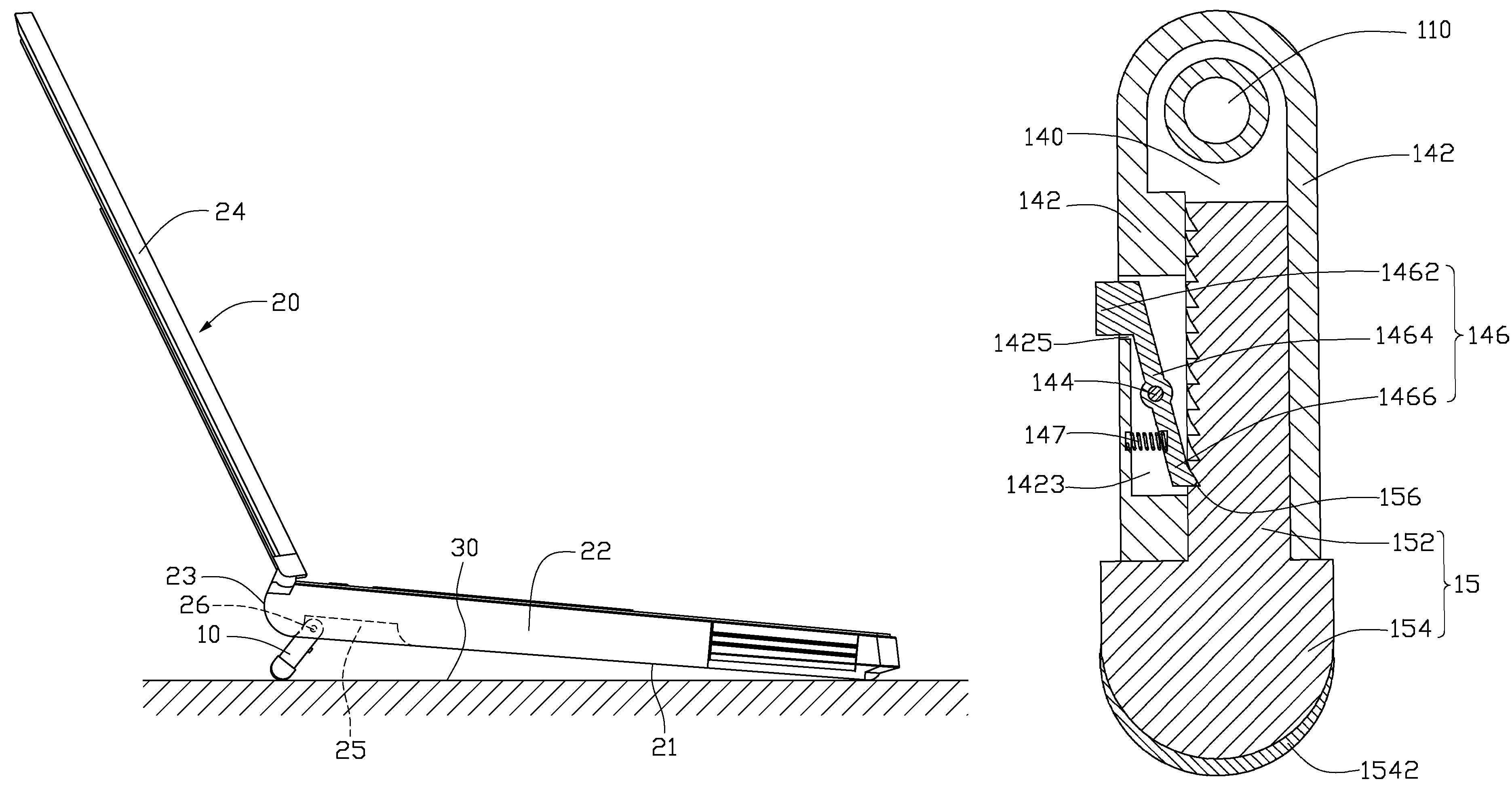
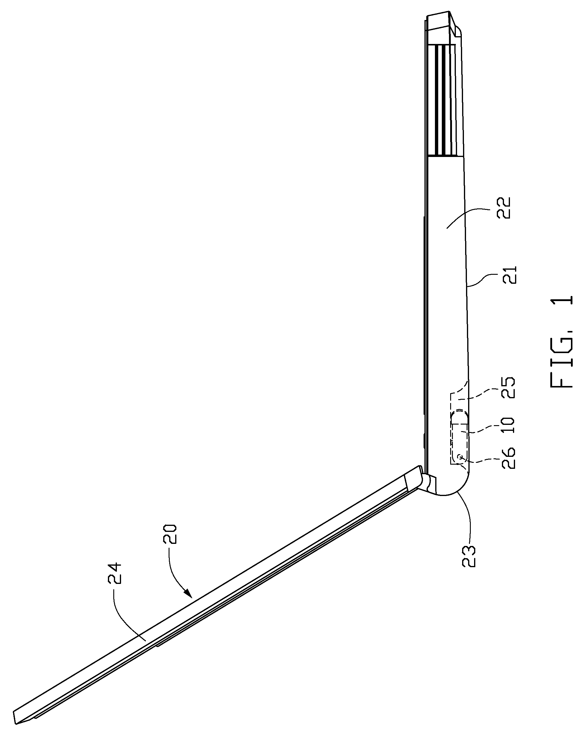
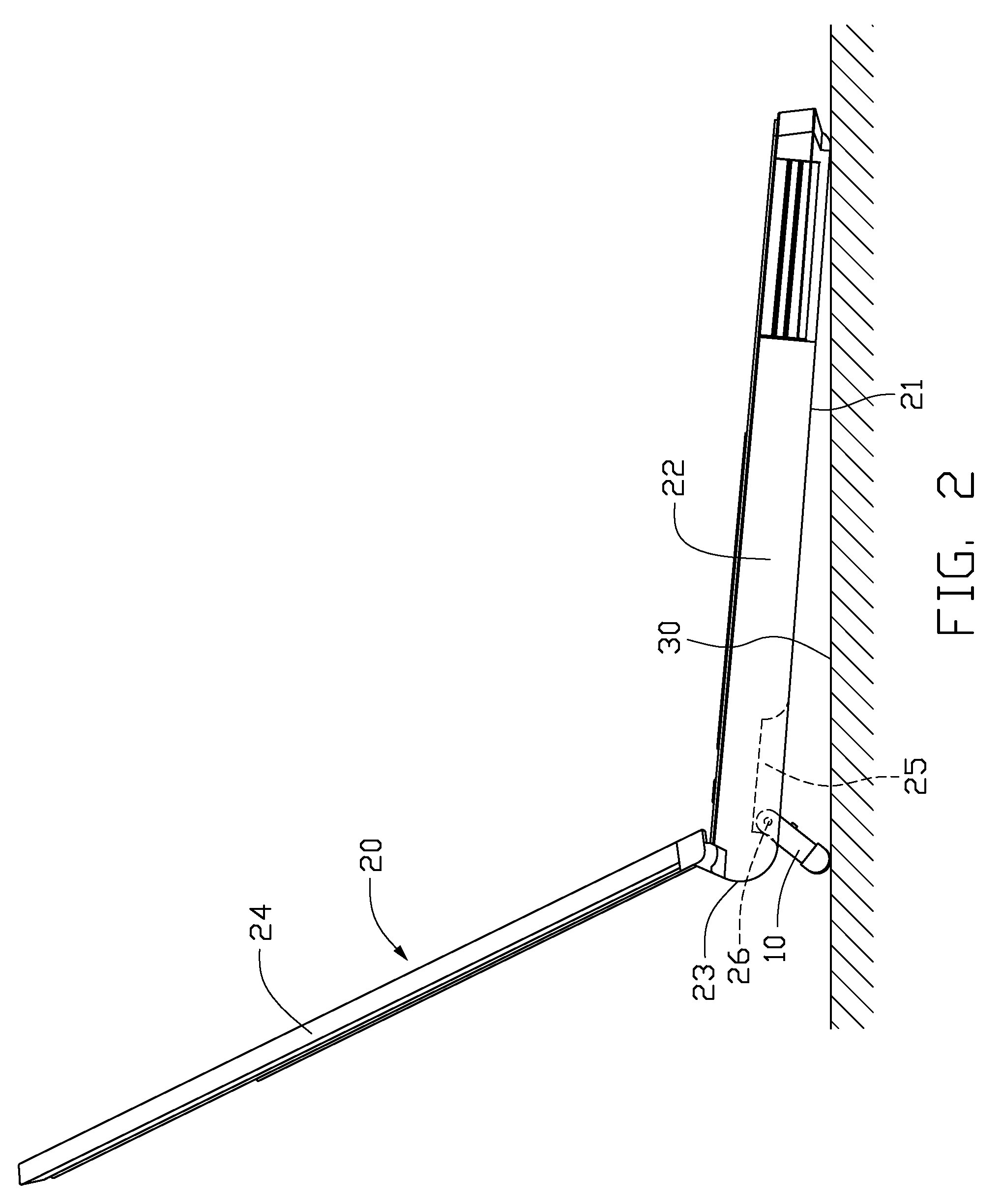
[0014]The present invention relates to an angle regulator whose length can be adjusted according to needs of different users, and an equipment with such an angle regulator. Referring to FIG. 1 and FIG. 2, an angle regulator 10 in accordance with a preferred embodiment of the present invention is designed to attach to a bottom surface 21 of a notebook computer 20 for providing an inclined angle towards the users for improving viewing and ergonomics. The notebook computer 20 is placed horizontally on a supporting surface 30 and includes a main body 22, a screen 24 pivotably connected to a lateral rear side of the main body 22 and two angle regulators 10 mounted to the bottom surface 21 of the main body 22. From the user's view, the two angle regulators 10 are respectively located at a left side and a right side of the main body 22 symmetrically, wherein only one angle regulator 10 is visible in FIG. 1 and FIG. 2 since FIGS. 1 and 2 are both side views of the notebook computer 20. The ...


PUM


Abstract

An angle regulator (10) includes an outer shell (14) having a deflecting arm (146) and an inner supporting pole (15) received in the outer shell. The deflecting arm includes a main rod (1464), and a press-button (1462) and a hook (1466) respectively located at two opposite ends of the main rod. The press-button extends from the main rod and protrudes out of the outer shell. A plurality of spaced grooves (156) are defined in the inner supporting pole along an axial direction thereof. When the press-button is pressed, the hook is detached from one of the grooves that is engaged with the hook such that the inner supporting pole can slide with respect to the outer shell, and when the press-button is released, the hook is selectively engaged in another one of the grooves so that the inner supporting pole and the outer shell are fixed to each other.

Description

BACKGROUND OF THE INVENTION[0001]1. Field of the Invention[0002]The present invention relates generally to angle regulators, and more particularly to an angle regulator assembled with an equipment to support the equipment with an inclined angle and to adjust the inclined angle to assume various angles towards an equipment user for improving ergonomics. The present invention also relates to an equipment with the angle regulator.[0003]2. Description of Related Art[0004]With the continued development of computer technology, various computers such as notebook computers or desktop computers are widespreadly used in all trades and occupations. The notebook computer and the keyboard of the desktop computer are generally putted horizontally on a table when using, a top surface of the table and a bottom of the notebook computer or the keyboard of the desktop computer are always fully contacted to each other, which tends to make users become fatigued easily for holding a same posture for a lo...

Claims


Application Information

Patent Timeline
Patent Type & Authority Patents(United States)
IPC IPC(8): F16M13/00
CPCG06F1/166G06F1/1616
Inventor CHEN, YEN-CHIH
Owner HON HAI PRECISION IND CO LTD
Why Eureka
Try Eureka